Cirkit Designer
Your all-in-one circuit design IDE
Home /
Project Documentation
Arduino UNO and Power Profiler Kit II Based Power Monitoring System with USB Connectivity
Circuit Documentation
Summary
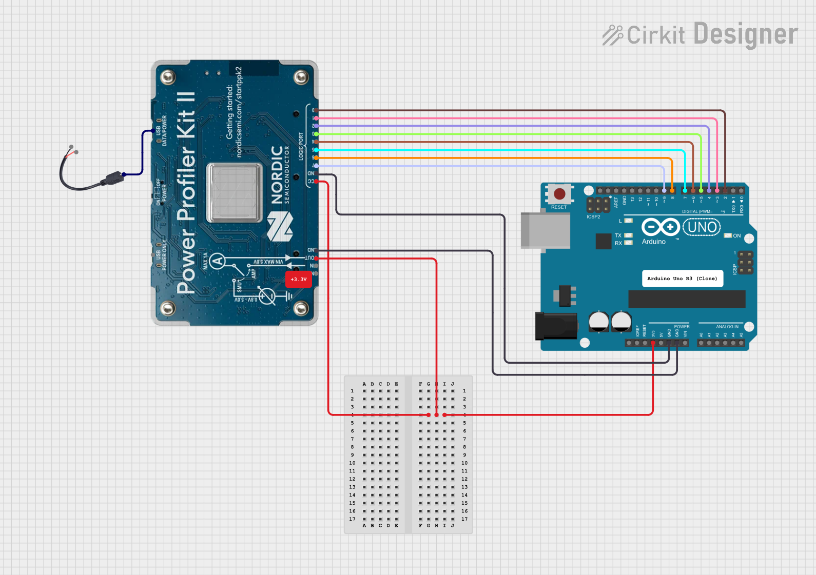
This document provides a detailed overview of a circuit that includes an Arduino UNO, a Power Profiler Kit II, and a Micro USB to Cable (2 Pin). The circuit is designed to interface the Arduino UNO with the Power Profiler Kit II for power profiling and data acquisition. The Micro USB to Cable (2 Pin) is used to connect the Power Profiler Kit II to a USB source.
Component List
Arduino UNO
- Description: A microcontroller board based on the ATmega328P.
- Pins: UNUSED, IOREF, Reset, 3.3V, 5V, GND, Vin, A0, A1, A2, A3, A4, A5, SCL, SDA, AREF, D13, D12, D11, D10, D9, D8, D7, D6, D5, D4, D3, D2, D1, D0
Power Profiler Kit II
- Description: A tool for power profiling and data acquisition.
- Pins: D0, D1, D2, D3, D4, D5, D6, D7, GND, VCC, USB D/P, USB P, VOUT, VIN
Micro USB to Cable (2 Pin)
- Description: A cable to connect a micro USB to a 2-pin interface.
- Pins: Micro USB, +, -
Comment
- Description: Placeholder for comments in the circuit.
- Pins: None
Wiring Details
Arduino UNO
- 3.3V is connected to VOUT and VCC of the Power Profiler Kit II.
- D2 is connected to D0 of the Power Profiler Kit II.
- D3 is connected to D1 of the Power Profiler Kit II.
- D4 is connected to D2 of the Power Profiler Kit II.
- D5 is connected to D3 of the Power Profiler Kit II.
- D6 is connected to D4 of the Power Profiler Kit II.
- D7 is connected to D5 of the Power Profiler Kit II.
- D8 is connected to D6 of the Power Profiler Kit II.
- D9 is connected to D7 of the Power Profiler Kit II.
- GND is connected to GND of the Power Profiler Kit II.
Power Profiler Kit II
- VOUT and VCC are connected to 3.3V of the Arduino UNO.
- D0 is connected to D2 of the Arduino UNO.
- D1 is connected to D3 of the Arduino UNO.
- D2 is connected to D4 of the Arduino UNO.
- D3 is connected to D5 of the Arduino UNO.
- D4 is connected to D6 of the Arduino UNO.
- D5 is connected to D7 of the Arduino UNO.
- D6 is connected to D8 of the Arduino UNO.
- D7 is connected to D9 of the Arduino UNO.
- GND is connected to GND of the Arduino UNO.
- USB D/P is connected to Micro USB of the Micro USB to Cable (2 Pin).
Micro USB to Cable (2 Pin)
- Micro USB is connected to USB D/P of the Power Profiler Kit II.
Documented Code
Arduino UNO Code
void setup() {
  // put your setup code here, to run once:

}

void loop() {
  // put your main code here, to run repeatedly:

}
Additional Documentation
This document provides a comprehensive overview of the circuit, including the components used, their connections, and the code running on the Arduino UNO.