
Arduino UNO Based Sensor-Integrated Motorized Display System
View and Edit Project In Cirkit Designer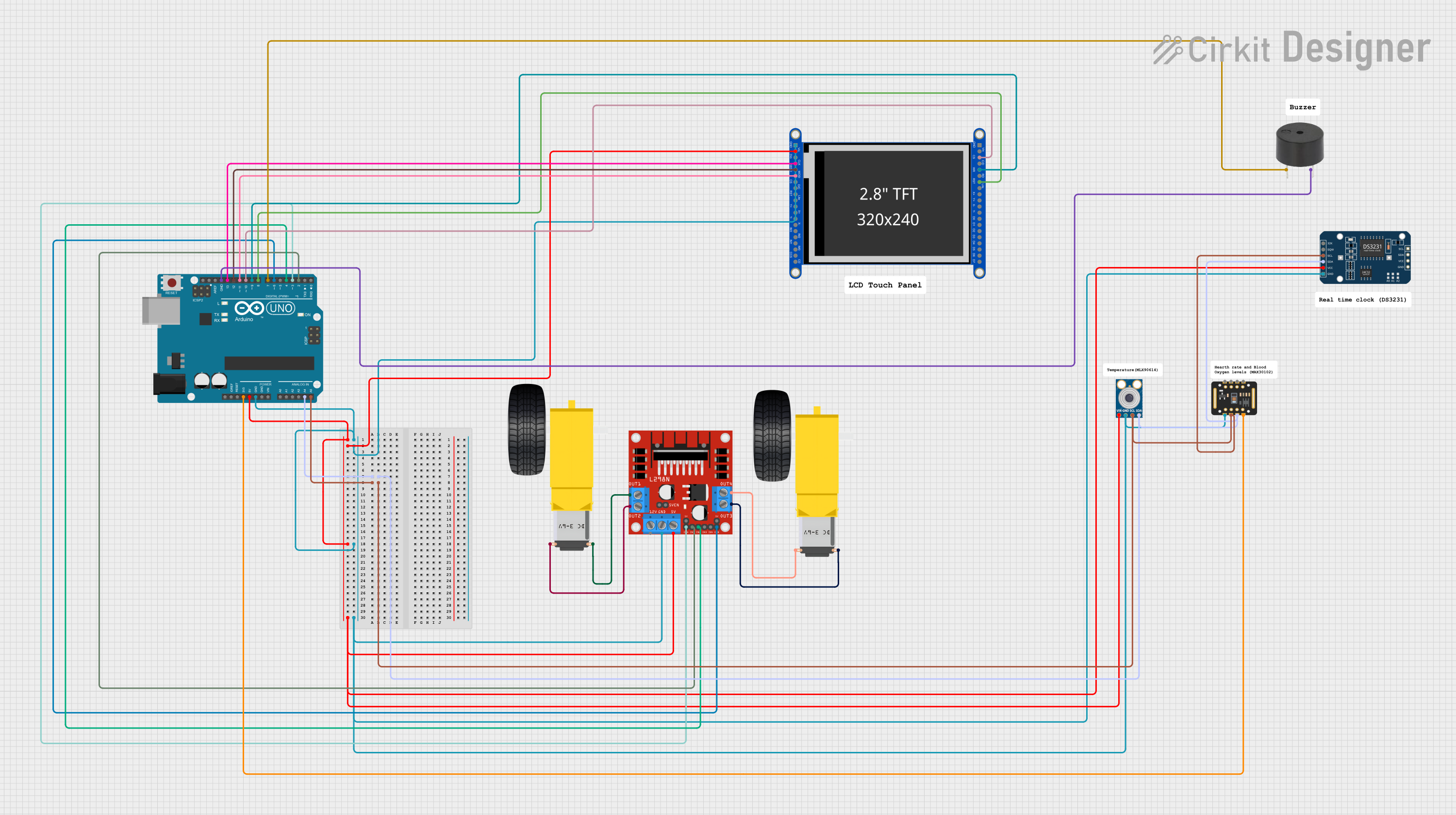
Circuit Documentation
Summary
This document provides a detailed overview of a circuit designed to interface various components with an Arduino UNO microcontroller. The circuit includes a display module, motor driver, DC gearmotors, temperature sensor, heart rate sensor, real-time clock, and a buzzer. The Arduino UNO serves as the central processing unit, controlling the inputs and outputs to the various peripherals. The circuit is powered by the Arduino's 5V and 3.3V outputs and includes an I2C communication bus for the sensors and RTC module.
Component List
Arduino UNO
- Microcontroller board based on the ATmega328P
- Provides digital and analog I/O pins
- Features I2C pins (A4, A5), SPI pins (D10-D13), and power outputs (3.3V, 5V)
Gearmotor DC Wheels Right (x2)
- DC gearmotors used for driving wheels
- Each motor has two connection pins
L298N DC Motor Driver
- H-Bridge motor driver capable of driving a pair of DC motors
- Provides motor control inputs and outputs, power inputs, and an enable jumper
Adafruit TFT 2.8 inch 320x240 Touch w/ microSD
- Color touchscreen display with microSD card slot
- Communicates with the Arduino via SPI and digital control pins
mlx90614
- Infrared temperature sensor
- Uses I2C communication
MAX30102
- Pulse oximetry and heart rate sensor
- Uses I2C communication and has interrupt and LED control pins
DS3231 RTC
- Real-time clock module
- Provides timekeeping via I2C communication
Buzzer
- Electromagnetic buzzer for audible alerts
- Controlled by a digital output from the Arduino
Wiring Details
Arduino UNO
5VandGNDpins provide power to the Adafruit TFT display, L298N motor driver, mlx90614 sensor, and DS3231 RTC.3.3Vpin provides power to the MAX30102 sensor.A4 (SDA)andA5 (SCL)are connected to the I2C bus, interfacing with the mlx90614, MAX30102, and DS3231 RTC.- Digital pins
D2toD13are used for controlling the L298N motor driver, Adafruit TFT display, and buzzer.
Gearmotor DC Wheels Right
- Two motors are controlled by the L298N motor driver, with each motor having two pins connected to the driver's output.
L298N DC Motor Driver
ENAandENBare connected to Arduino pinsD3andD6for enabling motor control.IN1,IN2,IN3, andIN4are connected to Arduino pinsD2,D4,D5, andD7for motor direction control.OUT1,OUT2,OUT3, andOUT4are connected to the gearmotor pins.
Adafruit TFT 2.8 inch 320x240 Touch w/ microSD
+5VandGNDfor power connections.SCLK,MISO,MOSI,LCD_CS,LCD_DC, andLCD_RSTare connected to Arduino pinsD13,D12,D11,D10,D9, andD8respectively for SPI communication and control.
mlx90614
SDAandSCLare connected to the I2C bus.VINandGNDare connected to5VandGNDon the Arduino for power.
MAX30102
SDAandSCLare connected to the I2C bus.VINis connected to3.3Von the Arduino, andGNDis connected toGND.
DS3231 RTC
SDAandSCLare connected to the I2C bus.VCCandGNDare connected to5VandGNDon the Arduino for power.
Buzzer
PINis connected to Arduino pinD7.GNDis connected toGNDon the Arduino.
Documented Code
Arduino UNO Code (sketch.ino)
void setup() {
  // put your setup code here, to run once:

}

void loop() {
  // put your main code here, to run repeatedly:

}
Additional Notes
- The provided code is a template and does not include specific functionality. It needs to be populated with the setup and loop functions to control the components as per the circuit design.
- The
documentation.txtfile is empty and does not contain any additional information.