Cirkit Designer
Your all-in-one circuit design IDE
Home /
Project Documentation
ESP32-Powered NTP Clock with Multiple GC9A01 Displays
Circuit Documentation
Summary
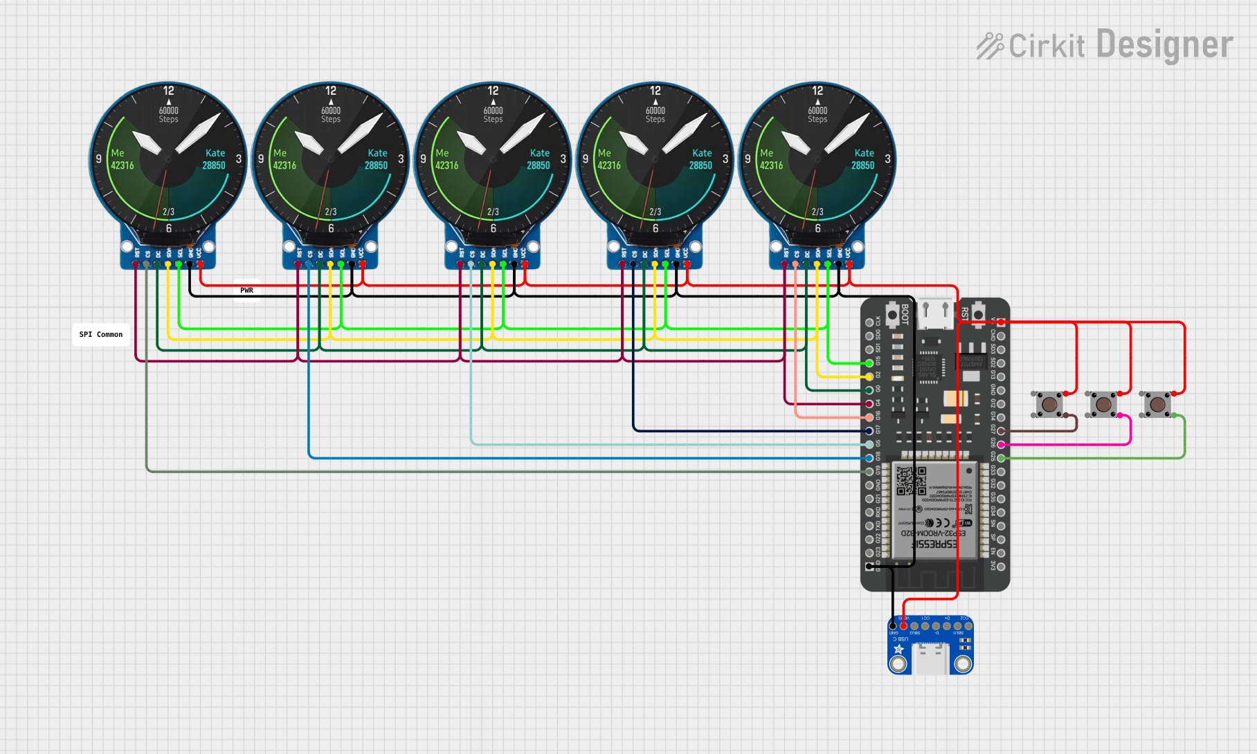
This circuit is designed to display the current time obtained from an NTP server on multiple GC9A01 displays. Each display shows one digit, with the middle display showing the HH:MM separator. The ESP32 microcontroller is used to connect to WiFi, obtain the time from the NTP server, and control the displays. Pushbuttons are included in the design, potentially for user input to control the display or settings.
Component List
ESP32 - 38 pins
- Description: A microcontroller with WiFi capability and a variety of GPIO pins.
- Purpose: Acts as the central processing unit of the circuit, handling WiFi communication, NTP time synchronization, and display control.
GC9A01 (Multiple Instances)
- Description: A round LCD display module.
- Purpose: Displays individual digits of the current time.
Pushbutton (Multiple Instances)
- Description: A simple pushbutton switch.
- Purpose: May be used for user input to control the display or settings.
Adafruit USB Type C Breakout
- Description: A breakout board for USB Type C connector.
- Purpose: Provides power to the circuit and potentially data connectivity.
Wiring Details
ESP32 - 38 pins
G25,G26,G27: Connected to the output pins of three different pushbuttons.5V: Connected to the VBUS pin of the Adafruit USB Type C Breakout and VCC pins of all GC9A01 displays.GND: Common ground with the Adafruit USB Type C Breakout and all GC9A01 displays.G19,G18,G5,G17,G16: Connected to the CS (Chip Select) pins of the GC9A01 displays.G4: Connected to the RST (Reset) pins of all GC9A01 displays.G0: Connected to the DC (Data/Command) pins of all GC9A01 displays.G2: Connected to the SDA (Serial Data) pins of all GC9A01 displays.G15: Connected to the SCL (Serial Clock) pins of all GC9A01 displays.
GC9A01 Displays
VCC: Connected to the 5V supply from the ESP32 and USB Type C Breakout.GND: Connected to the common ground.CS: Connected to individual GPIO pins on the ESP32 for chip select.RST: All connected to a single GPIO pin on the ESP32 for reset.DC: All connected to a single GPIO pin on the ESP32 for data/command selection.SDA: All connected to a single GPIO pin on the ESP32 for serial data.SCL: All connected to a single GPIO pin on the ESP32 for serial clock.
Pushbuttons
Pin 3 (out): Each connected to a separate GPIO pin on the ESP32 (G25,G26,G27).Pin 1 (in): All connected to the 5V supply.
Adafruit USB Type C Breakout
VBUS: Connected to the 5V supply line.GND: Connected to the common ground.
Documented Code
/*
 * This Arduino Sketch obtains the current time from an NTP server and displays
 * it on multiple GC9A01 displays. Each display shows one digit, with the middle
 * display showing the HH:MM separator.
 */

#include <WiFi.h>
#include <NTPClient.h>
#include <WiFiUdp.h>
#include <Adafruit_GFX.h>
#include <Adafruit_GC9A01.h>

// WiFi credentials
const char* ssid = "your_SSID";
const char* password = "your_PASSWORD";

// NTP Client settings
WiFiUDP ntpUDP;
NTPClient timeClient(ntpUDP, "pool.ntp.org", 0, 60000);

// Display pins
#define RST_PIN 4
#define DC_PIN 0
#define CS_PINS {16, 17, 5, 18, 19}
#define SCL_PIN 15
#define SDA_PIN 2

// Display objects
Adafruit_GC9A01 displays[5] = {
  Adafruit_GC9A01(CS_PINS[0], DC_PIN, RST_PIN),
  Adafruit_GC9A01(CS_PINS[1], DC_PIN, RST_PIN),
  Adafruit_GC9A01(CS_PINS[2], DC_PIN, RST_PIN),
  Adafruit_GC9A01(CS_PINS[3], DC_PIN, RST_PIN),
  Adafruit_GC9A01(CS_PINS[4], DC_PIN, RST_PIN)
};

void setup() {
  // Initialize serial communication
  Serial.begin(115200);

  // Connect to WiFi
  WiFi.begin(ssid, password);
  while (WiFi.status() != WL_CONNECTED) {
    delay(1000);
    Serial.println("Connecting to WiFi...");
  }
  Serial.println("Connected to WiFi");

  // Initialize NTP client
  timeClient.begin();

  // Initialize displays
  for (int i = 0; i < 5; i++) {
    displays[i].begin();
    displays[i].setRotation(1);
    displays[i].fillScreen(GC9A01_BLACK);
  }
}

void loop() {
  // Update time from NTP server
  timeClient.update();
  String formattedTime = timeClient.getFormattedTime();

  // Extract hours and minutes
  String hours = formattedTime.substring(0, 2);
  String minutes = formattedTime.substring(3, 5);

  // Display hours and minutes on displays
  displays[0].setCursor(0, 0);
  displays[0].print(hours[0]);
  displays[1].setCursor(0, 0);
  displays[1].print(hours[1]);
  displays[2].setCursor(0, 0);
  displays[2].print(":");
  displays[3].setCursor(0, 0);
  displays[3].print(minutes[0]);
  displays[4].setCursor(0, 0);
  displays[4].print(minutes[1]);

  // Refresh displays
  for (int i = 0; i < 5; i++) {
    displays[i].display();
  }

  // Wait for a second before updating again
  delay(1000);
}
This code is responsible for connecting the ESP32 to a WiFi network, synchronizing the time with an NTP server, and controlling the GC9A01 displays to show the current time. Each display is initialized and updated in the loop to show the corresponding digit of the current time.