
Arduino Nano-Based Motion Tracking System with Bluetooth Connectivity
View and Edit Project In Cirkit Designer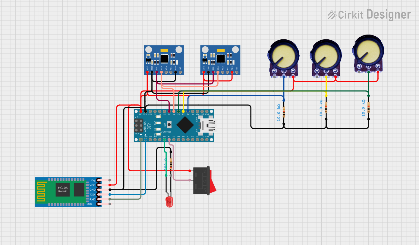
Circuit Documentation
Summary
This circuit integrates an Arduino Nano microcontroller with various peripherals including an HC-05 Bluetooth module, two MPU6050 Accelerometer + Gyroscope sensors, three potentiometers, a red LED, a rocker switch, and several resistors. The Arduino Nano serves as the central processing unit, interfacing with the sensors and modules to perform data acquisition and wireless communication. The potentiometers are likely used for input control or calibration, while the LED provides a visual output. The rocker switch may serve as a power switch or mode selector. The resistors are used for current limiting and pull-up/pull-down configurations.
Component List
Microcontroller
- Arduino Nano: A compact microcontroller board based on the ATmega328P, featuring digital and analog I/O pins.
Sensors
- MPU6050 Accelerometer + Gyroscope (Wokwi Compatible): A motion tracking device that combines a 3-axis gyroscope and a 3-axis accelerometer.
Communication Module
- HC-05 Bluetooth Module: A wireless communication module that enables Bluetooth connectivity for the circuit.
Input Devices
- Potentiometer: A variable resistor with three terminals, used to adjust voltage levels.
Output Devices
- LED: Two Pin (red): A red light-emitting diode used for visual indication.
Switches
- Rocker Switch: A binary switch with two positions, likely used for power control or mode selection.
Passive Components
- Resistor: A passive two-terminal electrical component that implements electrical resistance as a circuit element.
Wiring Details
Arduino Nano
- D1/TX connected to HC-05 Bluetooth Module RXD
- D0/RX connected to HC-05 Bluetooth Module TXD
- D3 connected to LED anode
- D4 connected to Rocker Switch pin 2
- A5 connected to MPU6050 SCL pins
- A4 connected to MPU6050 SDA pins
- A3 connected to Potentiometer Output (with Resistor in series)
- A2 connected to Potentiometer Output (with Resistor in series)
- A1 connected to Potentiometer Output (with Resistor in series)
- VIN connected to Rocker Switch pin 1 and various VCC pins
- GND connected to various GND pins
MPU6050 Accelerometer + Gyroscope
- VCC connected to Rocker Switch pin 1
- GND connected to Arduino Nano GND
- SCL connected to Arduino Nano A5
- SDA connected to Arduino Nano A4
HC-05 Bluetooth Module
- RXD connected to Arduino Nano D1/TX
- TXD connected to Arduino Nano D0/RX
- VCC connected to Rocker Switch pin 1
- GND connected to Arduino Nano GND
Potentiometer
- VCC connected to Rocker Switch pin 1
- Output connected to Arduino Nano analog pins (A1, A2, A3) with a Resistor in series
- GND connected to Arduino Nano GND
Resistor
- pin1 connected to Potentiometer Output or MPU6050 AD0
- pin2 connected to Arduino Nano analog pins (A1, A2, A3) or LED cathode
LED: Two Pin (red)
- anode connected to Arduino Nano D3
- cathode connected to Resistor pin2
Rocker Switch
- pin1 connected to Arduino Nano VIN and various VCC pins
- pin2 connected to Arduino Nano D4
Documented Code
sketch.ino
void setup() {
  // put your setup code here, to run once:

}

void loop() {
  // put your main code here, to run repeatedly:

}
documentation.txt
The documentation.txt file is empty and does not contain any additional information.