
Arduino UNO Controlled Robot with Ultrasonic Sensor and L293D Motor Driver
View and Edit Project In Cirkit Designer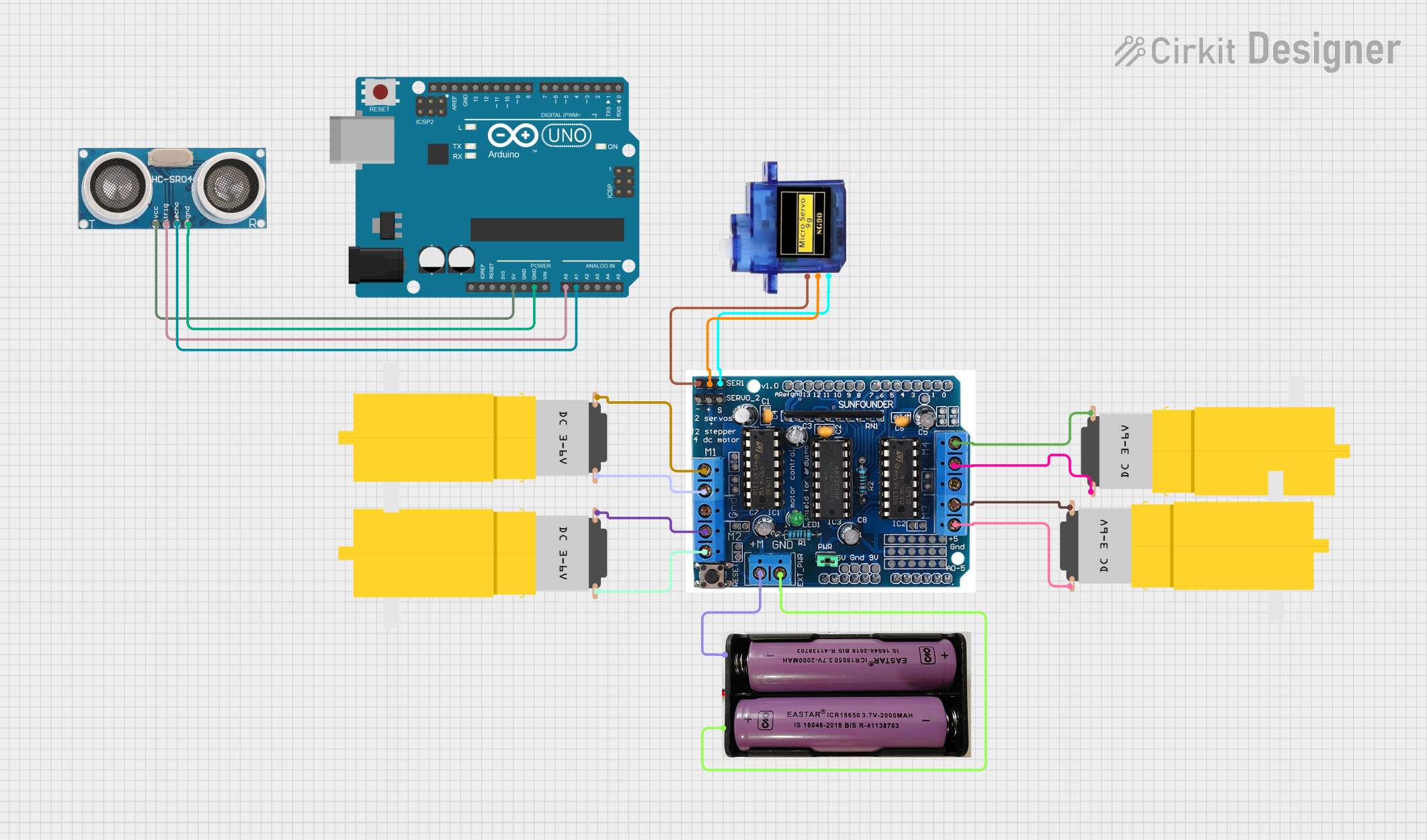
Circuit Documentation
Summary
This document provides a detailed overview of a circuit designed to interface an Arduino UNO with various peripherals including motors, an ultrasonic sensor, and a micro servo. The circuit utilizes a motor driver shield to control the motors and a power source to supply the necessary voltage. The ultrasonic sensor is connected to the Arduino for distance measurement, and the micro servo is controlled via PWM.
Component List
Arduino UNO
- Microcontroller board based on the ATmega328P
- It has 14 digital input/output pins, 6 analog inputs, a 16 MHz quartz crystal, a USB connection, a power jack, an ICSP header, and a reset button.
Motor Amarillo Motorreductor Hobby (x4)
- A yellow hobby gear motor
- It operates on a typical voltage, suitable for interfacing with the motor driver shield.
Ultrasonic Sensor
- A sensor that measures distance by emitting ultrasonic waves and measuring the time taken for the echo to return.
- Typically used in robotics for obstacle avoidance and distance measurement.
L293D Motor Driver Shield
- A motor driver shield that can drive up to 4 DC motors with individual 8-bit speed selection (0-255).
- It also has pins for 2 servo motors controlled by Arduino's PWM pins.
7.4V Battery
- A power source used to supply the motors through the motor driver shield.
- It provides the necessary voltage for motor operation.
Micro Servo 9G
- A small and lightweight servo motor suitable for applications that require simple motion.
- Controlled by PWM signal.
Wiring Details
Arduino UNO
- 5V connected to Ultrasonic Sensor VCC
- GND connected to Ultrasonic Sensor GND
- A0 connected to Ultrasonic Sensor Trigger
- A1 connected to Ultrasonic Sensor Echo
Motor Amarillo Motorreductor Hobby
- vcc connected to L293D Motor Driver Shield M1, M2, M3, M4 (one motor per channel)
- GND connected to L293D Motor Driver Shield M1, M2, M3, M4 (one motor per channel)
Ultrasonic Sensor
- +VCC connected to Arduino UNO 5V
- GND connected to Arduino UNO GND
- Trigger connected to Arduino UNO A0
- Echo connected to Arduino UNO A1
L293D Motor Driver Shield
- M+ connected to 7.4V Battery -
- GND connected to 7.4V Battery +
- M1, M2, M3, M4 connected to respective Motor Amarillo Motorreductor Hobby vcc and GND
- ser1 connected to Micro Servo 9G PWM
- + connected to Micro Servo 9G +5V
- - connected to Micro Servo 9G GND
7.4V Battery
- + connected to L293D Motor Driver Shield GND
- - connected to L293D Motor Driver Shield M+
Micro Servo 9G
- GND connected to L293D Motor Driver Shield -
- +5V connected to L293D Motor Driver Shield +
- PWM connected to L293D Motor Driver Shield ser1
Documented Code
Arduino UNO Code (sketch.ino)
void setup() {
  // put your setup code here, to run once:

}

void loop() {
  // put your main code here, to run repeatedly:

}
Note: The provided code is a template and does not include specific functionality. It should be populated with the necessary setup and loop code to control the connected components.