
ESP32-S3 Controlled Multi-Channel Relay System with ULN2803 Darlington Arrays
View and Edit Project In Cirkit Designer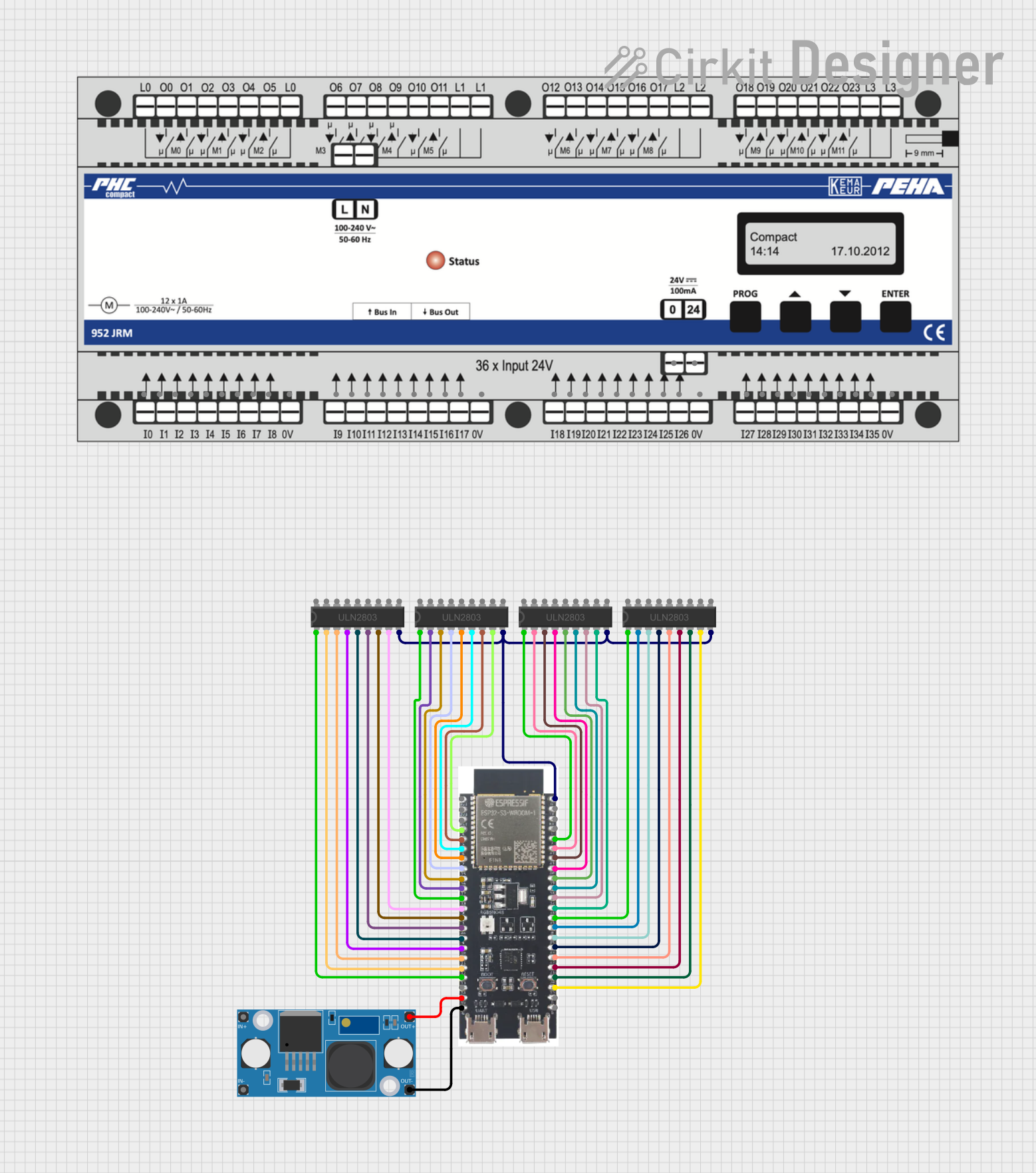
Circuit Documentation
Summary
This document provides a detailed overview of a circuit that primarily consists of multiple ULN2803 Darlington Array ICs, an ESP32-S3 microcontroller, and an LM2596 Step Down Module. The ESP32-S3 microcontroller is responsible for controlling the inputs to the Darlington arrays, which in turn drive various loads connected to their outputs. The LM2596 module steps down the voltage to a level suitable for powering the ESP32-S3. The circuit appears to be designed for controlling multiple outputs, possibly for driving relays, motors, or other high-current devices.
Component List
ULN2803 Darlington Array
- Description: An 8-channel Darlington transistor array with common-cathode flyback diodes for switching inductive loads.
- Pins: 18 pins including 8 inputs (I1-I8), 8 outputs (O1-O8), Ground (GND), and Common (COMMON).
ESP32-S3
- Description: A microcontroller with Wi-Fi and Bluetooth capabilities, suitable for a wide range of applications and advanced features.
- Pins: 38 pins including power (3v3, GND, 5V), enable (EN), and multiple general-purpose input/output (GPIO) pins.
LM2596 Step Down Module
- Description: A voltage regulator module that steps down input voltage to a lower output voltage.
- Pins: 4 pins including input voltage (IN+ and IN-) and output voltage (OUT+ and OUT-).
PEHA 952 JRE
- Description: A component with multiple input pins, possibly a sensor array or input interface.
- Pins: 36 pins including inputs (i0-i35), ground (0V), and power (24V).
Wiring Details
ULN2803 Darlington Array
- Inputs (I1-I8) are connected to various GPIO pins on the ESP32-S3.
- Outputs (O1-O8) are not detailed in the net list but would typically connect to the loads being driven.
- Ground (GND) is connected to the ESP32-S3 ground.
- Common (COMMON) is not detailed in the net list but would typically be connected to the positive voltage supply for the loads.
ESP32-S3
- GPIO pins are connected to the inputs of the ULN2803 Darlington Arrays to control the outputs.
- Ground (GND) is connected to the ground pins of all ULN2803 Darlington Arrays and the LM2596 Step Down Module.
- 5V pin is connected to the OUT+ of the LM2596 Step Down Module to power the microcontroller.
LM2596 Step Down Module
- OUT+ is connected to the 5V pin of the ESP32-S3 to provide power.
- OUT- is connected to the GND pin of the ESP32-S3 to complete the power circuit.
Documented Code
Microcontroller Code (ESP32-S3)
void setup() {
  // put your setup code here, to run once:

}

void loop() {
  // put your main code here, to run repeatedly:

}
Filename: sketch.ino
This code template is for the ESP32-S3 microcontroller. It contains the basic structure for an Arduino sketch with empty setup() and loop() functions. The setup() function is intended to contain initialization code that runs once, while the loop() function is designed to contain the main logic of the program that runs repeatedly.
Note: The actual logic for controlling the ULN2803 Darlington Arrays should be implemented within these functions, but the provided code does not include these details.
Additional Documentation (ESP32-S3)
There is an additional text file mentioned for documentation purposes, but no content was provided.
Filename: documentation.txt
This concludes the documentation for the provided circuit. Further details on the specific loads being driven by the ULN2803 Darlington Arrays and the exact wiring of the COMMON pins would be necessary for a complete understanding of the circuit's functionality.