Arduino-Based Automatic Plant Irrigation System with Rain Detection
Automatic Plant Irrigation System Documentation
Summary
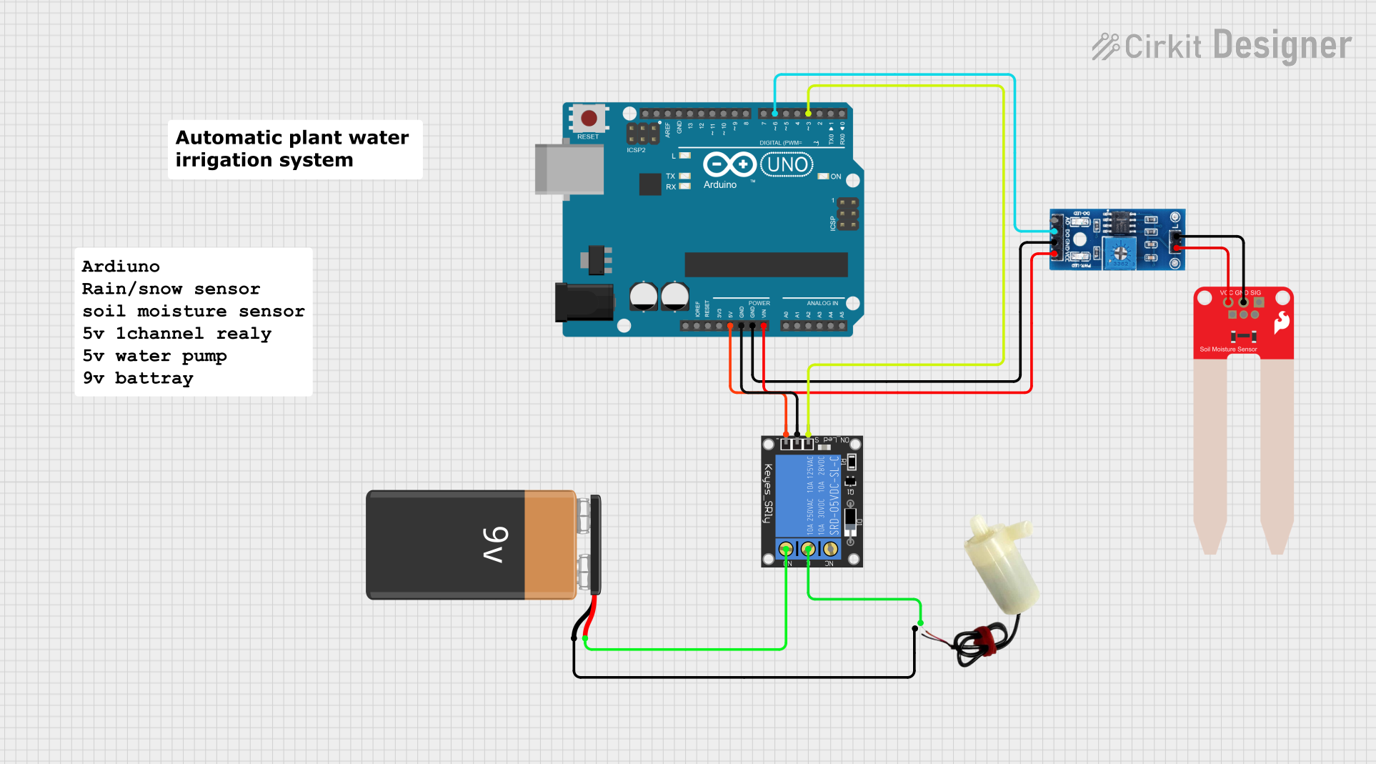
The Automatic Plant Irrigation System is designed to automate the watering process for plants based on soil moisture levels and weather conditions. The system utilizes an Arduino UNO microcontroller to monitor inputs from a rain/snow sensor and a soil moisture sensor. When the soil is dry and there is no rain detected, the system activates a 5V mini water pump through a 1-channel relay to water the plants. The system is powered by a 9V battery.
Component List
Arduino UNO
- Microcontroller board based on the ATmega328P
- Features digital and analog I/O pins
- Provides power output pins and ground connections
1-Channel Relay (5V 10A)
- Electromechanical switch controlled by an electrical signal
- Has Normally Open (NO) and Normally Closed (NC) contacts
- Used to control high power devices like the water pump
Rain/Snow Sensor - Board
- Detects the presence of rain or snow
- Provides both analog and digital outputs
- Digital output used to interface with the Arduino
SparkFun Soil Moisture Sensor
- Measures the moisture content in the soil
- Outputs an analog signal proportional to the moisture level
9V Battery
- Provides power to the circuit
- Used to drive the water pump through the relay
5V Mini Water Pump
- Operates at 5V to pump water
- Activated by the relay when the soil is dry and there is no rain
Wiring Details
Arduino UNO
5Vpin connected to the ground pin of the 1-Channel RelayGNDpin connected to the power pin of the 1-Channel RelayVinpin connected to the VCC (5V) pin of the Rain/Snow SensorD6pin connected to the D0 (Digital) pin of the Rain/Snow SensorD3pin connected to the signal pin of the 1-Channel Relay
1-Channel Relay (5V 10A)
groundpin connected to the 5V pin of the Arduino UNOpowerpin connected to the GND pin of the Arduino UNOsignalpin connected to the D3 pin of the Arduino UNOCpin connected to the positive pin of the 5V mini water pumpNOpin connected to the + pin of the 9V Battery
Rain/Snow Sensor - Board
GNDpin connected to the GND pin of the Arduino UNOVCC (5V)pin connected to the Vin pin of the Arduino UNOD0 (Digital)pin connected to the D6 pin of the Arduino UNO1pin connected to the GND pin of the SparkFun Soil Moisture Sensor2pin connected to the VCC pin of the SparkFun Soil Moisture Sensor
SparkFun Soil Moisture Sensor
GNDpin connected to the1pin of the Rain/Snow SensorVCCpin connected to the2pin of the Rain/Snow Sensor
9V Battery
+pin connected to the NO pin of the 1-Channel Relay-pin connected to the negative pin of the 5V mini water pump
5V Mini Water Pump
positive pinconnected to the C pin of the 1-Channel Relaynegative pinconnected to the - pin of the 9V Battery
Documented Code
/*
 * Automatic Plant Irrigation System
 *
 * This Arduino sketch controls an automatic plant irrigation system. It uses a
 * rain/snow sensor to detect moisture and a soil moisture sensor to monitor the
 * soil's moisture level. If the soil is dry and it is not raining, the system
 * activates a water pump via a relay to water the plants.
 */

// Pin definitions
const int rainSensorPin = 6; // Digital pin connected to rain sensor
const int soilMoisturePin = A0; // Analog pin connected to soil moisture sensor
const int relayPin = 3; // Digital pin connected to relay

// Soil moisture threshold
const int soilMoistureThreshold = 500;

void setup() {
  // Initialize serial communication
  Serial.begin(9600);

  // Initialize pin modes
  pinMode(rainSensorPin, INPUT);
  pinMode(soilMoisturePin, INPUT);
  pinMode(relayPin, OUTPUT);

  // Ensure the relay is off initially
  digitalWrite(relayPin, LOW);
}

void loop() {
  // Read the rain sensor value
  int rainSensorValue = digitalRead(rainSensorPin);
  // Read the soil moisture sensor value
  int soilMoistureValue = analogRead(soilMoisturePin);

  // Print sensor values to the serial monitor
  Serial.print("Rain Sensor: ");
  Serial.print(rainSensorValue);
  Serial.print("\tSoil Moisture: ");
  Serial.println(soilMoistureValue);

  // Check if it is not raining and the soil is dry
  if (rainSensorValue == LOW && soilMoistureValue < soilMoistureThreshold) {
    // Turn on the relay to activate the water pump
    digitalWrite(relayPin, HIGH);
  } else {
    // Turn off the relay to deactivate the water pump
    digitalWrite(relayPin, LOW);
  }

  // Wait for a second before the next loop
  delay(1000);
}
This code is responsible for reading the sensor inputs and controlling the relay based on the predefined conditions. The rainSensorPin is set to digital pin 6, which corresponds to the digital output of the rain/snow sensor. The soilMoisturePin is set to analog pin A0, which is connected to the soil moisture sensor. The relayPin is set to digital pin 3, which controls the relay module. The system reads the sensor values, prints them to the serial monitor, and activates the water pump if the conditions are met.