
Circuit Documentation
Summary of the Circuit
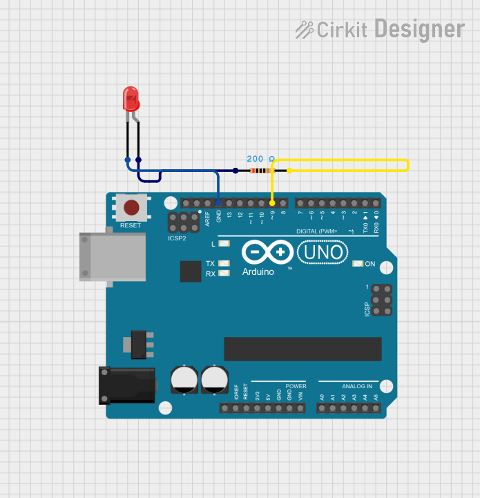
This circuit consists of an Arduino UNO microcontroller, a red two-pin LED, and a resistor. The purpose of the circuit is to control the brightness of the LED using Pulse Width Modulation (PWM) provided by the Arduino UNO. The LED's brightness is varied in a fading pattern, which is achieved by incrementally changing the PWM value on a digital pin of the Arduino.
Component List
Arduino UNO
- Description: A microcontroller board based on the ATmega328P.
- Pins Used: GND, D9
- Purpose: Acts as the main controller for the circuit, providing PWM output to control the LED brightness.
LED: Two Pin (red)
- Description: A basic red light-emitting diode.
- Pins Used: cathode, anode
- Purpose: Emits light when powered, with brightness controlled by the Arduino UNO.
Resistor
- Description: A passive two-terminal electrical component that implements electrical resistance.
- Value: 200 Ohms
- Pins Used: pin1, pin2
- Purpose: Limits the current flowing through the LED to prevent damage.
Wiring Details
Arduino UNO
- GND: Connected to the cathode of the LED.
- D9: Connected to pin2 of the Resistor.
LED: Two Pin (red)
- cathode: Connected to GND on the Arduino UNO.
- anode: Connected to pin1 of the Resistor.
Resistor
- pin1: Connected to the anode of the LED.
- pin2: Connected to D9 on the Arduino UNO.
Documented Code
// Code for Arduino UNO
// Filename: sketch.ino

int led = 9;         // the PWM pin the LED is attached to
int brightness = 0;  // how bright the LED is
int fadeAmount = 5;  // how many points to fade the LED by

// the setup routine runs once when you press reset:
void setup() {
  // declare pin 9 to be an output:
  pinMode(led, OUTPUT);
}

// the loop routine runs over and over again forever:
void loop() {
  // set the brightness of pin 9:
  analogWrite(led, brightness);

  // change the brightness for next time through the loop:
  brightness = brightness + fadeAmount;

  // reverse the direction of the fading at the ends of the fade:
  if (brightness <= 0 || brightness >= 255) {
    fadeAmount = -fadeAmount;
  }
  // wait for 30 milliseconds to see the dimming effect
  delay(30);
}
This code is designed to run on the Arduino UNO microcontroller. It initializes pin 9 as an output and uses it to control the brightness of the connected LED through PWM. The brightness variable is altered on each iteration of the loop function, causing the LED to fade in and out. The fadeAmount determines the rate of fading, and the direction of the fade is reversed when the brightness reaches its minimum or maximum value.