Wi-Fi Controlled Robotic Arm with Live Video Streaming

Circuit Documentation
Summary
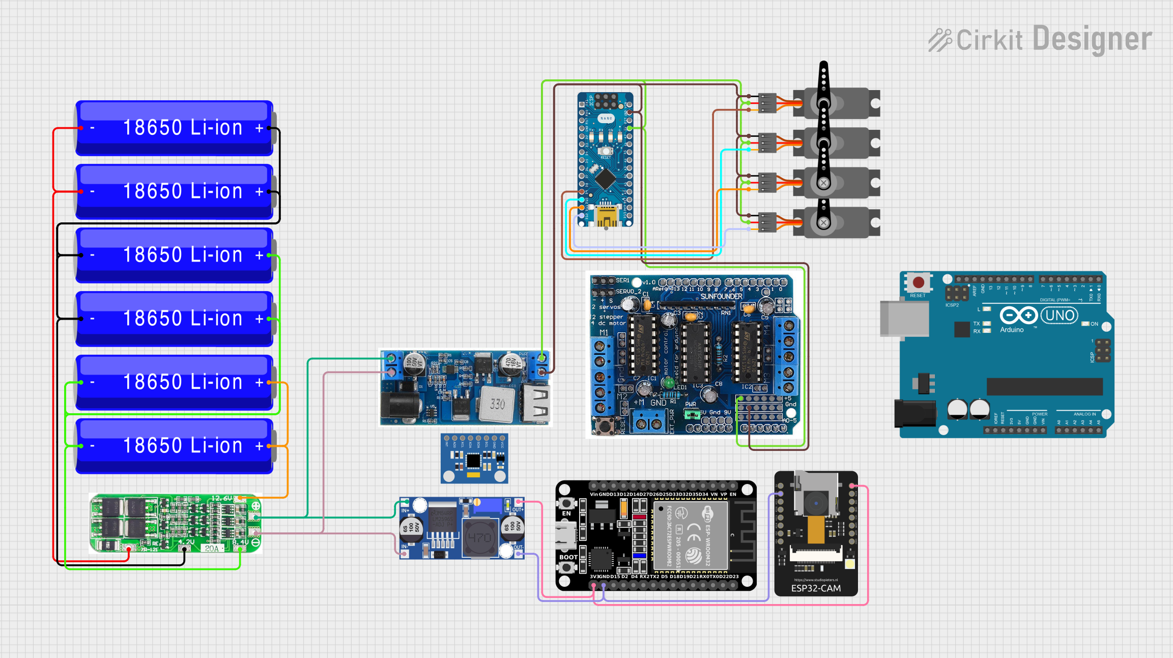
This circuit integrates a variety of components including microcontrollers (Arduino UNO, Arduino Nano, ESP32, ESP32-CAM), power management modules (24/12v Buck converter, Buck converter, 3s 20A BMS), sensors (MPU6050 Accelerometer + Gyroscope), actuators (Servos), and power sources (18650 Li-ion Batteries). The circuit is designed to control multiple servos via the Arduino Nano, manage power distribution with buck converters and a battery management system, and interface with ESP32 modules for additional functionality.
Component List
Microcontrollers
- Arduino UNO: A microcontroller board based on the ATmega328P, commonly used for building digital devices and interactive objects.
- Arduino Nano: A small, complete, and breadboard-friendly board based on the ATmega328P, used for similar applications as the UNO but in a smaller form factor.
- ESP32 (30 pin): A powerful microcontroller with Wi-Fi and Bluetooth capabilities, suitable for a wide variety of applications from low-power sensor networks to more demanding tasks.
- ESP32 - CAM: A small camera module with an ESP32-S chip that besides the Wi-Fi functionality also provides Bluetooth capabilities.
Power Management
- 24/12v Buck Converter: A step-down (buck) converter that reduces voltage from 24V or 12V to a lower voltage, typically 5V.
- Buck Converter: A generic step-down converter for voltage regulation in the circuit.
- 3s 20A BMS (Battery Management System): Manages a 3-cell series battery pack, providing overcharge, over-discharge, and short-circuit protection.
Sensors
- MPU6050 Accelerometer + Gyroscope (Wokwi Compatible): A sensor module that provides motion tracking data, commonly used in drones, robotics, and other motion-sensitive applications.
Actuators
- Servo: An actuator capable of precise control of angular or linear position, velocity, and acceleration, commonly used for steering mechanisms in radio-controlled vehicles.
Power Sources
- 18650 Li-ion Battery: A standard size for rechargeable lithium-ion batteries, used in laptops, flashlights, and electric vehicles.
Motor Drivers
- l293d driver shield: A motor driver shield that can drive up to 4 DC motors or 2 stepper motors, 2 servos, and has 8 half-bridges.
Wiring Details
Arduino UNO
Arduino Nano
- D9: Connected to Servo (PWM)
- D10: Connected to Servo (PWM)
- D11/MOSI: Connected to Servo (PWM)
- D12/MISO: Connected to Servo (PWM)
- GND: Common ground with Servos, 24/12v Buck, and l293d driver shield
- 5V: Power supply to Servos and l293d driver shield from 24/12v Buck
ESP32 (30 pin)
ESP32 - CAM
- 3V3: Receives 3.3V from Buck Converter
- GND: Common ground with Buck Converter and ESP32 (30 pin)
24/12v Buck Converter
- VIN+: Connected to 3s 20A BMS (+) and Buck Converter (IN+)
- VIN-: Connected to 3s 20A BMS (-) and Buck Converter (IN-)
- 5V: Supplies power to Servos, Arduino Nano, and l293d driver shield
- GND: Common ground with Servos, Arduino Nano, and l293d driver shield
Buck Converter
- IN+: Connected to 24/12v Buck (VIN+)
- IN-: Connected to 24/12v Buck (VIN-)
- OUT+: Supplies 3.3V to ESP32 - CAM and ESP32 (30 pin)
- OUT-: Common ground with ESP32 - CAM and ESP32 (30 pin)
MPU6050 Accelerometer + Gyroscope (Wokwi Compatible)
Servos
- PWM: Controlled by Arduino Nano (D9, D10, D11/MOSI, D12/MISO)
- VCC: Powered by 24/12v Buck (5V)
- GND: Common ground with 24/12v Buck, Arduino Nano, and l293d driver shield
3s 20A BMS
- DV/GND: Connected to 18650 Li-ion Batteries (-)
- 4.2V: Connected to 18650 Li-ion Batteries (+)
- 8.4V: Connected to 18650 Li-ion Batteries (-)
- 12.6V: Connected to 18650 Li-ion Batteries (+)
- +: Connected to 24/12v Buck (VIN+)
- -: Connected to 24/12v Buck (VIN-)
18650 Li-ion Batteries
- +: Connected to 3s 20A BMS (4.2V, 8.4V, 12.6V)
- -: Connected to 3s 20A BMS (DV/GND, 8.4V)
l293d driver shield
Documented Code
Arduino UNO Code
void setup() {
  // put your setup code here, to run once:

}

void loop() {
  // put your main code here, to run repeatedly:

}
Filename: sketch.ino
Arduino Nano Code
void setup() {
  // put your setup code here, to run once:

}

void loop() {
  // put your main code here, to run repeatedly:

}
Filename: sketch.ino
(Note: The provided code for both Arduino UNO and Arduino Nano is a template and does not contain any functional code specific to the circuit's operation. Additional code is required to control the servos, read sensors, manage power, and communicate with the ESP32 modules.)