
Arduino UNO Smart Motion-Activated Light with Photocell and PIR Sensor
View and Edit Project In Cirkit Designer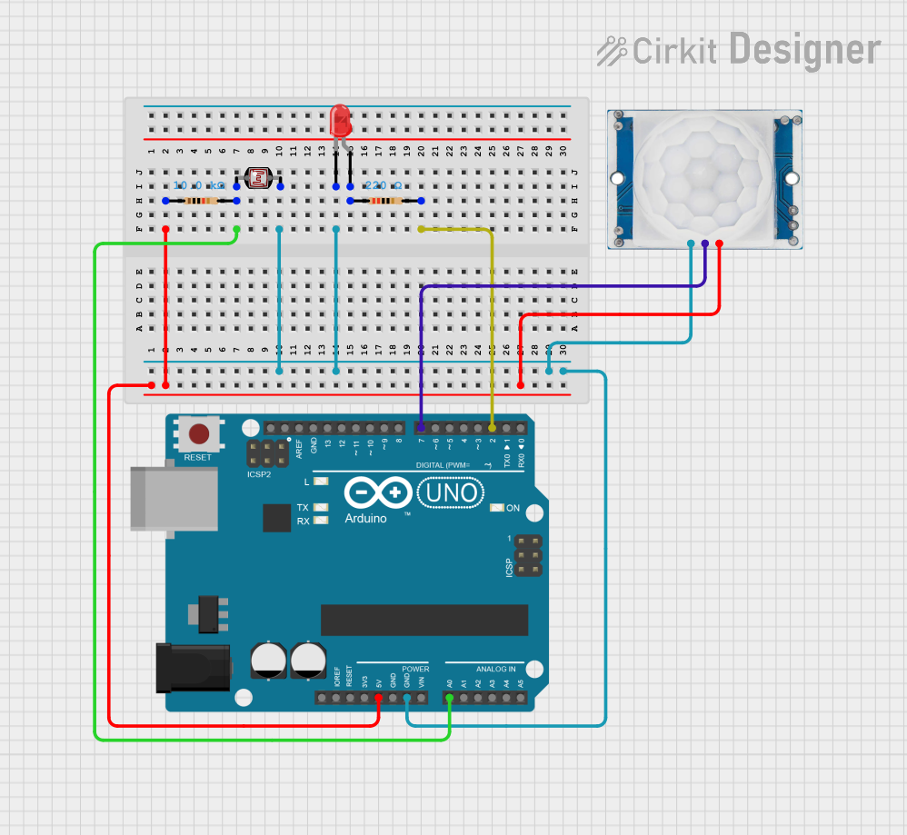
Circuit Documentation
Summary
This circuit is designed to detect motion using a PIR sensor and measure light intensity using a photocell (LDR). The circuit includes an Arduino UNO microcontroller, which processes the sensor inputs and controls an LED indicator. The LED lights up based on the sensor inputs.
Component List
LED: Two Pin (red)
- Description: A red LED used as an indicator.
- Pins: Cathode, Anode
Resistor (220 Ohms)
- Description: A resistor with a resistance of 220 Ohms.
- Pins: Pin1, Pin2
Photocell (LDR)
- Description: A light-dependent resistor used to measure light intensity.
- Pins: Pin 0, Pin 1
Resistor (10k Ohms)
- Description: A resistor with a resistance of 10k Ohms.
- Pins: Pin1, Pin2
Arduino UNO
- Description: A microcontroller board based on the ATmega328P.
- Pins: UNUSED, IOREF, Reset, 3.3V, 5V, GND, Vin, A0, A1, A2, A3, A4, A5, SCL, SDA, AREF, D13, D12, D11, D10, D9, D8, D7, D6, D5, D4, D3, D2, D1, D0
HC-SR501 PIR Motion Sensor
- Description: A passive infrared sensor used to detect motion.
- Pins: Output, Ground, Power Supply
Wiring Details
LED: Two Pin (red)
- Anode is connected to Pin1 of the 220 Ohm Resistor.
- Cathode is connected to:
- Pin 1 of the Photocell (LDR)
- Ground of the HC-SR501 PIR Motion Sensor
- GND of the Arduino UNO
Resistor (220 Ohms)
- Pin1 is connected to the Anode of the LED.
- Pin2 is connected to D2 of the Arduino UNO.
Photocell (LDR)
- Pin 0 is connected to:
- Pin2 of the 10k Ohm Resistor
- A0 of the Arduino UNO
- Pin 1 is connected to the Cathode of the LED.
Resistor (10k Ohms)
- Pin1 is connected to:
- 5V of the Arduino UNO
- Power Supply of the HC-SR501 PIR Motion Sensor
- Pin2 is connected to Pin 0 of the Photocell (LDR).
Arduino UNO
- 5V is connected to:
- Pin1 of the 10k Ohm Resistor
- Power Supply of the HC-SR501 PIR Motion Sensor
- GND is connected to:
- Cathode of the LED
- Ground of the HC-SR501 PIR Motion Sensor
- A0 is connected to Pin 0 of the Photocell (LDR).
- D2 is connected to Pin2 of the 220 Ohm Resistor.
- D7 is connected to the Output of the HC-SR501 PIR Motion Sensor.
HC-SR501 PIR Motion Sensor
- Power Supply is connected to:
- 5V of the Arduino UNO
- Pin1 of the 10k Ohm Resistor
- Ground is connected to:
- Cathode of the LED
- GND of the Arduino UNO
- Output is connected to D7 of the Arduino UNO.
Documented Code
sketch.ino
void setup() {
  // put your setup code here, to run once:

}

void loop() {
  // put your main code here, to run repeatedly:

}
documentation.txt
This documentation provides a comprehensive overview of the circuit, including a summary, detailed component list, wiring details, and the code used in the microcontroller.