
Circuit Documentation
Summary of the Circuit
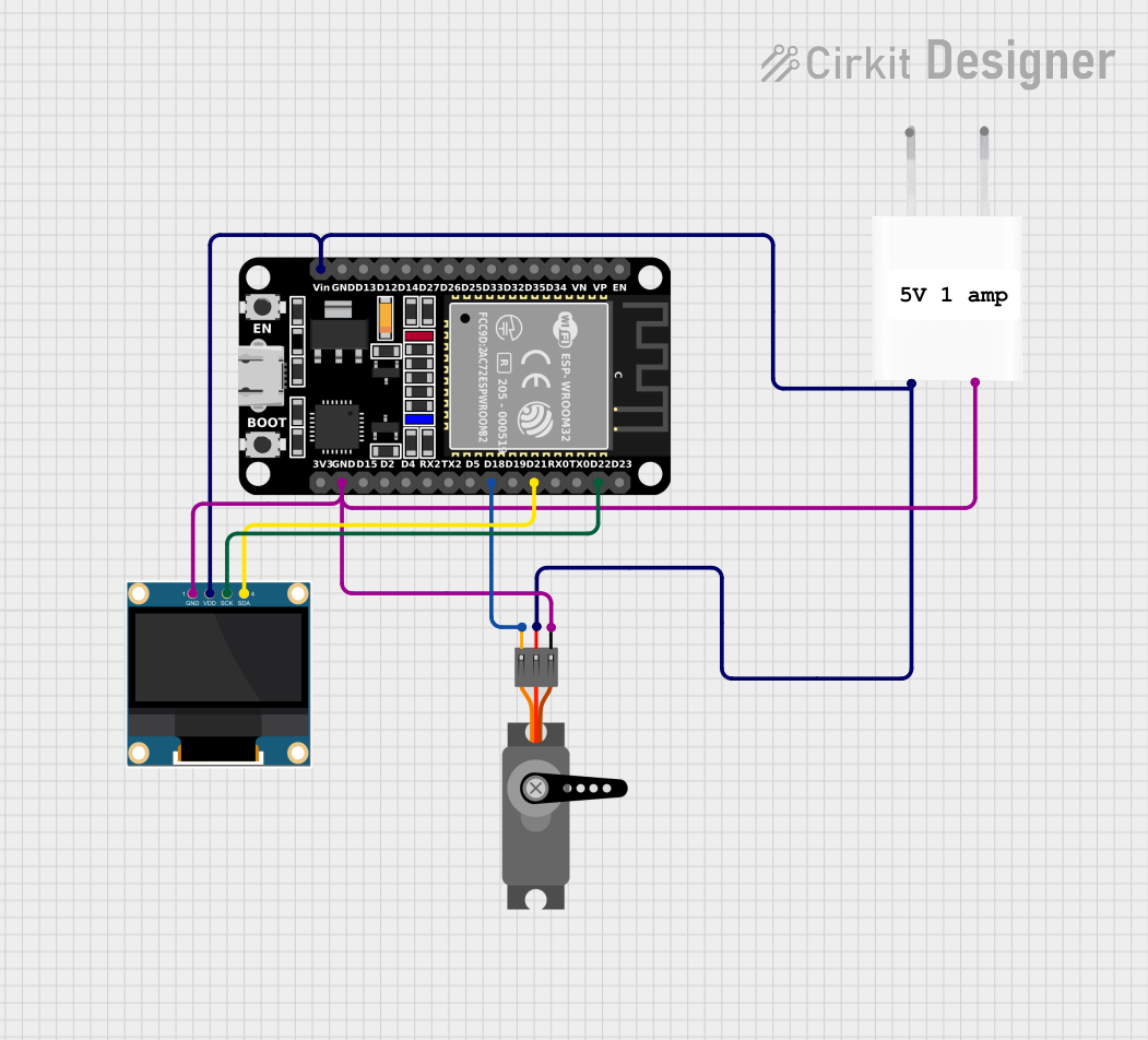
This circuit integrates an ESP32 microcontroller with a 0.96" OLED display and a servo motor, powered by a 5V adapter. The ESP32 serves as the central processing unit, controlling the OLED display via I2C communication and the servo motor through a PWM signal. The 5V adapter provides a stable power supply to all components in the circuit.
Component List
ESP32 (30 pin)
- Description: A microcontroller with Wi-Fi and Bluetooth capabilities, featuring a variety of GPIO pins for interfacing with peripherals.
- Pins: EN, VP, VN, D34, D35, D32, D33, D25, D26, D27, D14, D12, D13, GND, Vin, D23, D22, TX0, RX0, D21, D19, D18, D5, TX2, RX2, D4, D2, D15, 3V3
0.96" OLED
- Description: A small display that uses the OLED technology for high contrast and visibility.
- Pins: GND, VDD, SCK, SDA
Servo
- Description: An actuator that can be precisely controlled in terms of the angle of rotation.
- Pins: GND, VCC, PWM
5V Adapter
- Description: A power supply unit that converts AC to a 5V DC output.
- Pins: AC In 1, AC In 2, 5V, GND
Wiring Details
ESP32 (30 pin)
- Vin connected to the 5V output from the 5V Adapter.
- GND connected to the common ground net.
- D22 (SCK) connected to the SCK pin of the 0.96" OLED for I2C communication.
- D21 (SDA) connected to the SDA pin of the 0.96" OLED for I2C communication.
- D18 (PWM) connected to the PWM pin of the Servo to control its position.
0.96" OLED
- VDD connected to the 5V output from the 5V Adapter.
- GND connected to the common ground net.
- SCK connected to the D22 pin of the ESP32 for I2C communication.
- SDA connected to the D21 pin of the ESP32 for I2C communication.
Servo
- VCC connected to the 5V output from the 5V Adapter.
- GND connected to the common ground net.
- PWM connected to the D18 pin of the ESP32 for PWM control.
5V Adapter
- 5V output connected to the Vin pin of the ESP32, VDD pin of the 0.96" OLED, and VCC pin of the Servo.
- GND connected to the common ground net.
Common Ground Net
- The GND pins of the ESP32, 0.96" OLED, Servo, and 5V Adapter are all interconnected.
Documented Code
No code has been provided for the microcontroller. When code is available, it should be documented here with explanations for each function and routine, including setup and loop functions, I2C communication setup, and PWM signal generation for servo control.