
Arduino-Controlled Stepper Motor with Speed and Direction Control
View and Edit Project In Cirkit Designer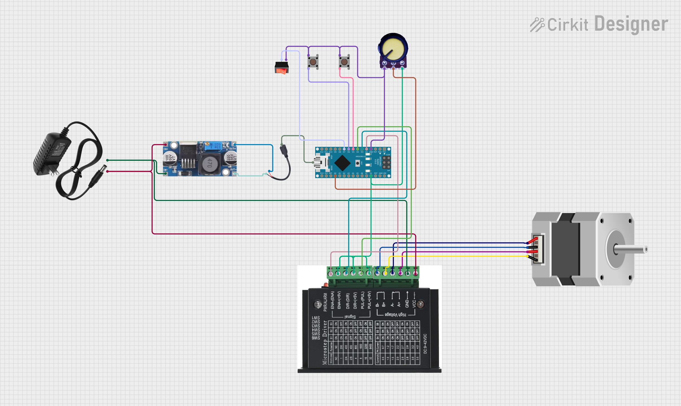
Circuit Documentation
Summary
This circuit is designed to control a bipolar stepper motor using an Arduino Nano microcontroller. The system's operation is influenced by user inputs from a potentiometer, a toggle switch, and two pushbuttons. The potentiometer adjusts the motor speed, the toggle switch enables or disables the system, and the pushbuttons determine the motor's rotation direction. A stepper driver interfaces the Arduino with the stepper motor, receiving power from a 12V power supply through a step-down buck converter. The circuit also includes a micro USB to cable connector for powering the Arduino Nano.
Component List
STEPPER DRIVER
- Description: A device that drives a bipolar stepper motor by amplifying the control signals from the microcontroller.
- Pins: ENA -, ENA +, DIR -, DIR+, PUL -, PUL +, B-, B+, A-, A+, GND, VCC
Stepper Motor (Bipolar)
- Description: A bipolar stepper motor that is controlled by the stepper driver.
- Pins: D, B, C, A
Arduino Nano
- Description: A compact microcontroller board based on the ATmega328P, used to generate control signals for the stepper driver and read inputs from the potentiometer, toggle switch, and pushbuttons.
- Pins: D1/TX, D0/RX, RESET, GND, D2, D3, D4, D5, D6, D7, D8, D9, D10, D11/MOSI, D12/MISO, VIN, 5V, A7, A6, A5, A4, A3, A2, A1, A0, AREF, 3V3, D13/SCK
12V Power Supply
- Description: Provides the primary power source for the stepper driver.
- Pins: +, -
Step Down Buck Converter
- Description: Converts the 12V input from the power supply to a lower voltage suitable for the Arduino Nano and other components.
- Pins: IN +, IN - GND, OUT +, OUT - GND
Micro USB to Cable (2 Pin)
- Description: Provides a connection for powering the Arduino Nano via USB.
- Pins: Micro USB, +, -
Pushbutton (x2)
- Description: User input devices that send signals to the Arduino Nano to control the stepper motor's direction.
- Pins: Pin 3 (out), Pin 4 (out), Pin 1 (in), Pin 2 (in)
Potentiometer
- Description: A variable resistor that provides an analog input to the Arduino Nano to control the stepper motor's speed.
- Pins: GND, Output, VCC
Rocker Switch
- Description: A switch that allows the user to enable or disable the system.
- Pins: Output, Input
Wiring Details
STEPPER DRIVER
- ENA - connected to Arduino Nano D2
- ENA +, DIR+, PUL + connected to Potentiometer VCC and Arduino Nano 5V
- DIR - connected to Arduino Nano D3
- PUL - connected to Arduino Nano D4
- B- connected to Stepper Motor (Bipolar) C
- B+ connected to Stepper Motor (Bipolar) D
- A- connected to Stepper Motor (Bipolar) A
- A+ connected to Stepper Motor (Bipolar) B
- GND connected to Step down Buck converter IN - GND and 12v power supply -
- VCC connected to Step down Buck converter IN + and 12v power supply +
Stepper Motor (Bipolar)
- D, B, C, A connected to corresponding pins on STEPPER DRIVER
Arduino Nano
- D2, D3, D4 connected to corresponding pins on STEPPER DRIVER
- 5V connected to STEPPER DRIVER ENA +, DIR+, PUL +
- GND connected to Pushbuttons and Potentiometer GND
- D5 connected to Pushbutton Pin 2 (in)
- D6 connected to Pushbutton Pin 2 (in)
- D7 connected to Rocker Switch Output
- A0 connected to Potentiometer Output
- Micro USB connected to Micro USB to Cable (2 Pin) Micro USB
12V Power Supply
-
- connected to STEPPER DRIVER VCC and Step down Buck converter IN +
-
- connected to STEPPER DRIVER GND and Step down Buck converter IN - GND
Step Down Buck Converter
- IN +, IN - GND connected to 12V Power Supply and STEPPER DRIVER
- OUT + connected to Micro USB to Cable (2 Pin) +
- OUT - GND connected to Micro USB to Cable (2 Pin) -
Micro USB to Cable (2 Pin)
- Micro USB connected to Arduino Nano
- +, - connected to Step down Buck converter OUT +, OUT - GND
Pushbutton (x2)
- Pin 1 (in) connected to Arduino Nano GND
- Pin 2 (in) connected to Arduino Nano D5 (for one pushbutton) and D6 (for the other pushbutton)
Potentiometer
- GND connected to Arduino Nano GND
- Output connected to Arduino Nano A0
- VCC connected to STEPPER DRIVER ENA +, DIR+, PUL +
Rocker Switch
- Input connected to Pushbuttons and Potentiometer GND
- Output connected to Arduino Nano D7
Documented Code
/*
 * This Arduino Sketch controls a stepper motor using a potentiometer,
 * a toggle switch, and two push buttons. The potentiometer sets the speed,
 * the toggle switch enables/disables the system, and the push buttons
 * control the direction of the stepper motor.
 */

// Pin definitions
const int enaPin = 2;
const int dirPin = 3;
const int pulPin = 4;
const int moveLeftButtonPin = 5;
const int moveRightButtonPin = 6;
const int toggleSwitchPin = 7;
const int potPin = A0;

void setup() {
  // Initialize output pins
  pinMode(enaPin, OUTPUT);
  pinMode(dirPin, OUTPUT);
  pinMode(pulPin, OUTPUT);

  // Initialize input pins with internal pull-up resistors
  pinMode(moveLeftButtonPin, INPUT_PULLUP);
  pinMode(moveRightButtonPin, INPUT_PULLUP);
  pinMode(toggleSwitchPin, INPUT_PULLUP);

  // Potentiometer pin remains as INPUT
  pinMode(potPin, INPUT);

  // Enable the stepper driver
  digitalWrite(enaPin, LOW);
}

// Debounce function for the toggle switch
bool debounceSwitch(int pin) {
  bool currentState;
  bool previousState = digitalRead(pin); // Initial state
  delay(50); // 50 ms debounce delay (adjust as needed)
  currentState = digitalRead(pin); // Read state again after delay
  return currentState == previousState; // Return true if stable
}

void loop() {
  // Debounced system enable/disable logic
  bool systemEnabled = debounceSwitch(toggleSwitchPin);

  if (systemEnabled) {
    // Read the potentiometer value and map it to a delay
    int potValue = analogRead(potPin);
    int delayTime = map(potValue, 0, 1023, 1000, 100); // Speed control

    // Check the move left button
    if (digitalRead(moveLeftButtonPin) == LOW) {
      digitalWrite(dirPin, LOW); // Set direction to left
      stepMotor(delayTime);
    }
    // Check the move right button
    else if (digitalRead(moveRightButtonPin) == LOW) {
      digitalWrite(dirPin, HIGH); // Set direction to right
      stepMotor(delayTime);
    }
  }

  delay(1); // Small delay to avoid rapid looping
}

void stepMotor(int delayTime) {
  digitalWrite(pulPin, HIGH);
  delayMicroseconds(delayTime);
  digitalWrite(pulPin, LOW);
  delayMicroseconds(delayTime);
}
This code is designed to run on the Arduino Nano and controls the stepper motor's operation based on the inputs from the potentiometer, toggle switch, and pushbuttons. It includes functions for debouncing the toggle switch and stepping the motor at a speed determined by the potentiometer's position. The motor's direction is controlled by the state of the pushbuttons.