
ESP32-Based Audio Recorder and Playback System with Servo Control and LED Indicators
View and Edit Project In Cirkit Designer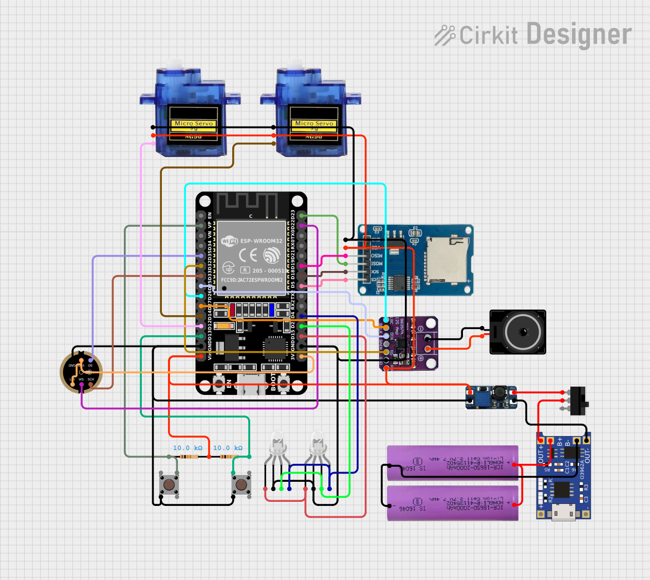
Circuit Documentation
Summary
This circuit integrates various components including microcontrollers, sensors, power management modules, actuators, and user interface elements. The primary controller is an ESP32 microcontroller, which interfaces with an INMP441 microphone, a Max98357 audio amplifier, a micro SD card module, micro servos, LEDs, and a pushbutton. Power management is handled by a TP4056 charging module and a DC-DC boost converter, with power supplied by Li-ion batteries. The circuit is designed to capture audio, control servos, store data on an SD card, and provide visual feedback through LEDs.
Component List
Microcontroller
- ESP32 (30 pin): A powerful microcontroller with Wi-Fi and Bluetooth capabilities, featuring a variety of digital and analog I/O pins.
Sensors
- INMP441 FRONT MIC: A high-quality MEMS microphone with I2S digital output.
Power Management
- DC-DC BOOST CONVERTOR: Steps up the voltage from the input to a higher, regulated output voltage.
- TP4056: A lithium-ion battery charger module with integrated battery protection.
- Li-ion battery 18650-2000mAh 3.7V 7.4WH: Provides power to the circuit.
Actuators
- Micro servo 9G: A small and lightweight servo motor for precise angular movement.
- Loudspeaker: Converts electrical signals into sound.
User Interface
- Pushbutton: A simple switch mechanism for control of a circuit.
- Toggle Switch: A switch that can maintain its state without continuous user interaction.
- LED: Four Pin (Common Cathode): A multi-color LED with individual control over red, green, and blue elements.
Storage
- Micro SD Card Module: Allows the microcontroller to read from and write to a micro SD card.
Audio Output
- Max98357: An I2S Class D audio amplifier for driving speakers.
Miscellaneous
- Resistor: A passive two-terminal electrical component that implements electrical resistance.
Wiring Details
ESP32 (30 pin)
- VP: Connected to a resistor and a pushbutton.
- D35: Connected to the SD pin of the INMP441 microphone.
- D32: Connected to the SD pin of the Max98357 audio amplifier.
- D33: Connected to the SCK pin of the INMP441 microphone.
- D25: Connected to the DIN pin of the Max98357 audio amplifier.
- D26: Connected to the LRC pin of the Max98357 audio amplifier.
- D27: Connected to the BLCK pin of the Max98357 audio amplifier.
- D14, D12: Connected to the PWM pins of the micro servos.
- D13: Connected to a resistor and a pushbutton.
- GND: Common ground for various components.
- Vin: Connected to the positive output of the DC-DC boost converter.
- D23, D22, D19, D18, D5: Connected to the respective pins of the micro SD card module.
- D4, D2, D15: Connected to the anode pins of the LEDs.
- 3V3: Connected to the VDD and L/R pins of the INMP441 microphone.
INMP441 FRONT MIC
- SD, SCK, WS: Connected to the ESP32.
- GND: Common ground.
- VDD, L/R: Connected to the 3V3 pin of the ESP32.
Max98357
- SD, DIN, LRC, BLCK: Connected to the ESP32.
- GND: Common ground.
- VIN: Connected to the positive output of the DC-DC boost converter.
- -, +: Connected to the loudspeaker.
Micro SD Card Module
- cs, sck, mosi, miso, vcc, gnd: Connected to the respective pins of the ESP32.
Micro servo 9G
- PWM: Connected to the ESP32.
- +5V: Connected to the positive output of the DC-DC boost converter.
- GND: Common ground.
Pushbutton
- Pin 3 (out), Pin 1 (in): Connected to the ESP32 and a resistor.
- Pin 2 (in): Connected to the common ground.
Toggle Switch
- L1: Connected to the positive input of the DC-DC boost converter.
- COM: Connected to the positive output of the TP4056.
DC-DC BOOST CONVERTOR
- VIN-: Connected to the OUT- of the TP4056.
- VIN+: Connected to the L1 of the Toggle Switch.
- VOUT+: Connected to the Vin of the ESP32 and other components requiring 5V.
- VOUT-: Common ground.
TP4056
- OUT-, B-: Connected to the negative terminals of the Li-ion batteries.
- B+: Connected to the positive terminals of the Li-ion batteries.
- OUT+: Connected to the COM of the Toggle Switch.
Li-ion battery 18650-2000mAh 3.7V 7.4WH
- +: Connected to the B+ of the TP4056.
- -: Connected to the B- of the TP4056.
Resistor
- pin1, pin2: Connected between the ESP32 and pushbuttons.
LED: Four Pin (Common Cathode)
- red anode, green anode, blue anode: Connected to the ESP32.
- common cathode: Connected to the common ground.
Loudspeaker
- pin1, pin2: Connected to the Max98357 audio amplifier.
Documented Code
No code was provided for the microcontrollers in the circuit. Therefore, this section is left blank until the relevant code is supplied.