
Raspberry Pi Controlled Multi-Stepper and Servo Motor System
View and Edit Project In Cirkit Designer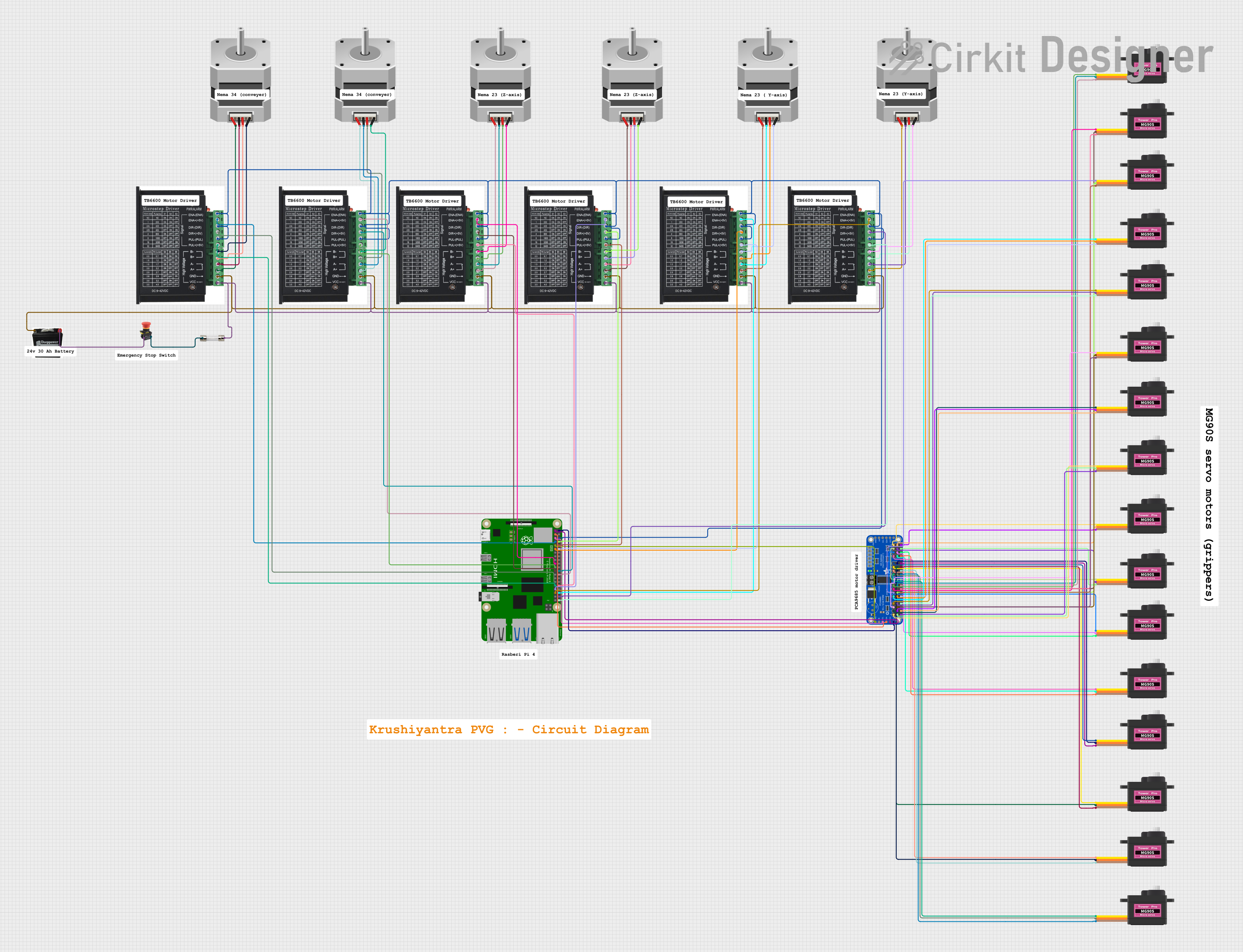
Circuit Documentation
Summary
This circuit is designed to control multiple stepper motors and servomotors using a Raspberry Pi 4B as the main microcontroller. The stepper motors are driven by dedicated stepper drivers, and the servomotors are controlled via an Adafruit PCA9685 PWM Servo Breakout board. The circuit includes an emergency stop mechanism and a battery with a 5A fuse for power management. The Raspberry Pi 4B is programmed to interface with the stepper drivers and the PWM Servo Breakout board to manage the motion of the motors.
Component List
- Stepper Motor (Bipolar): A type of motor that is driven by electric pulses and capable of precise position control.
- STEPPER DRIVER: A device that controls the operation of the stepper motor by translating the control signals into motor motion.
- Battery: Provides the power supply for the circuit.
- Servomotor MG90S: A small and lightweight servomotor used for precise control of angular or linear position, velocity, and acceleration.
- Adafruit PCA9685 PWM Servo Breakout: A 16-channel, 12-bit PWM Fm+ I2C-bus LED controller used for controlling multiple servomotors.
- Raspberry Pi 4B: A small computer that serves as the main controller for the circuit, capable of running code to control the motors.
- 5A Fuse: Protects the circuit from overcurrent by breaking the connection if the current exceeds 5 amperes.
- Emergency STOP: A safety mechanism that can cut off power to the motors in case of an emergency.
Wiring Details
Stepper Motors and Drivers
- Stepper Motor (Bipolar): Each motor has four pins (D, B, C, A) connected to the corresponding pins (B-, B+, A-, A+) on its respective STEPPER DRIVER.
STEPPER DRIVER
- ENA-, DIR-, PUL-: All negative control pins are connected to the ground (GND) of the Raspberry Pi 4B.
- ENA+, DIR+, PUL+: Each positive control pin is connected to a designated GPIO pin on the Raspberry Pi 4B for enabling, direction control, and pulse signal.
- GND: Connected to the negative terminal of the battery.
- VCC: Connected to the output of the 5A fuse, which is connected to the positive terminal of the battery.
Servomotors and Adafruit PCA9685 PWM Servo Breakout
- Servomotor MG90S:
- SIG: Connected to a PWM channel on the Adafruit PCA9685 PWM Servo Breakout.
- VCC: Connected to the 5.0V pin on the Adafruit PCA9685 PWM Servo Breakout.
- GND: Connected to the ground (GND) pin on the Adafruit PCA9685 PWM Servo Breakout.
Adafruit PCA9685 PWM Servo Breakout
- 5.0V: Connected to the 5V pin on the Raspberry Pi 4B.
- GND: Connected to the ground (GND) pin on the Raspberry Pi 4B.
- VCC: Connected to the 3V3 pin on the Raspberry Pi 4B.
- SDA, SCL: Connected to the corresponding SDA and SCL GPIO pins on the Raspberry Pi 4B for I2C communication.
Raspberry Pi 4B
- GPIO Pins: Connected to the positive control pins (ENA+, DIR+, PUL+) of the STEPPER DRIVERs and the SDA, SCL pins of the Adafruit PCA9685 PWM Servo Breakout.
Power Management
- Battery: Provides power to the circuit with the positive terminal connected through an Emergency STOP switch to a 5A fuse, and the negative terminal connected to the GND of the circuit.
- 5A Fuse: Connected between the Emergency STOP switch and the VCC of the STEPPER DRIVERs to protect against overcurrent.
Documented Code
Raspberry Pi 4B Code (sketch.ino)
void setup() {
  // put your setup code here, to run once:

}

void loop() {
  // put your main code here, to run repeatedly:

}
The code for the Raspberry Pi 4B is currently a template with empty setup() and loop() functions. The setup() function is intended for initialization code that runs once at startup, and the loop() function is for the main code that runs repeatedly. The actual implementation will depend on the specific control logic required for the stepper and servomotors.
Additional Documentation (documentation.txt)
There is an additional text file named documentation.txt mentioned in the code input, but it was provided without content. This file can be used to include detailed descriptions, usage instructions, or any other relevant information about the code and its operation within the circuit.