
ESP32 and L298N Motor Driver-Based Wi-Fi Controlled Robotic Car
View and Edit Project In Cirkit Designer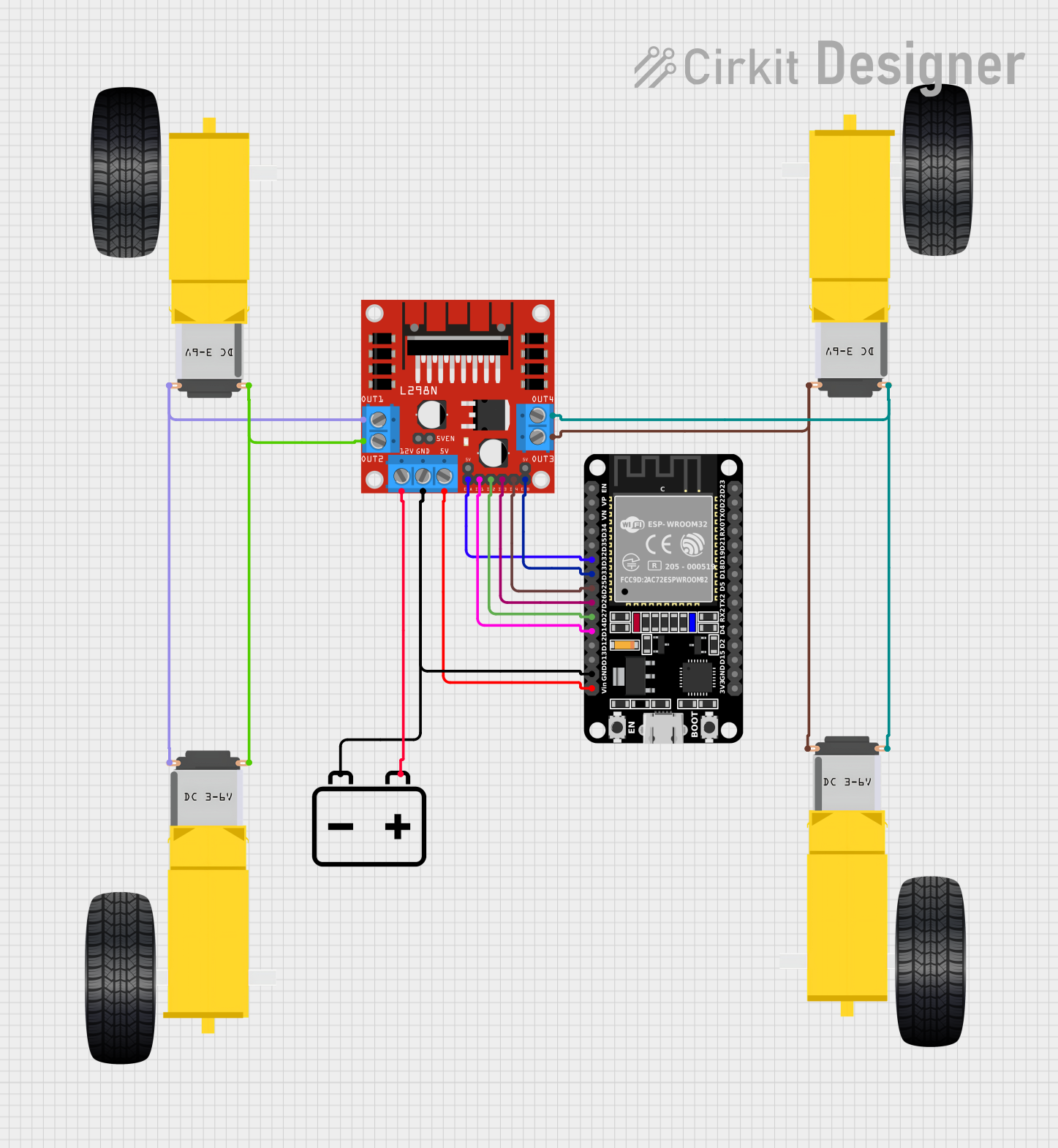
Circuit Documentation
Summary
This document provides a detailed overview of a circuit designed to control DC motors using an L298N motor driver and an ESP32 microcontroller. The circuit is powered by a 12V battery and includes multiple gearmotors for driving wheels.
Component List
L298N DC Motor Driver
- Description: A dual H-bridge motor driver that allows control of the speed and direction of two DC motors.
- Pins: OUT1, OUT2, 12V, GND, 5V, OUT3, OUT4, 5V-ENA-JMP-I, 5V-ENA-JMP-O, +5V-J1, +5V-J2, ENA, IN1, IN2, IN3, IN4, ENB
ESP32 (30 pin)
- Description: A low-cost, low-power system on a chip microcontroller with integrated Wi-Fi and dual-mode Bluetooth.
- Pins: EN, VP, VN, D34, D35, D32, D33, D25, D26, D27, D14, D12, D13, GND, Vin, D23, D22, TX0, RX0, D21, D19, D18, D5, TX2, RX2, D4, D2, D15, 3V3
12V Battery
- Description: A power source providing 12V DC.
- Pins: +, -
Gearmotor DC Wheels Right
- Description: A DC motor with attached wheels for driving the right side of a vehicle.
- Pins: PIN1, PIN2
Gearmotor DC Wheels Left
- Description: A DC motor with attached wheels for driving the left side of a vehicle.
- Pins: PIN1, PIN2
Wiring Details
L298N DC Motor Driver
- OUT1: Connected to PIN1 of Gearmotor DC Wheels Right and PIN2 of Gearmotor DC Wheels Left.
- OUT2: Connected to PIN2 of Gearmotor DC Wheels Right and PIN1 of Gearmotor DC Wheels Left.
- 12V: Connected to the + pin of the 12V Battery.
- GND: Connected to the - pin of the 12V Battery and GND pin of the ESP32.
- 5V: Connected to the Vin pin of the ESP32.
- OUT3: Connected to PIN2 of another Gearmotor DC Wheels Right and PIN1 of another Gearmotor DC Wheels Left.
- OUT4: Connected to PIN1 of another Gearmotor DC Wheels Right and PIN2 of another Gearmotor DC Wheels Left.
- ENA: Connected to D32 pin of the ESP32.
- IN1: Connected to D14 pin of the ESP32.
- IN2: Connected to D27 pin of the ESP32.
- IN3: Connected to D26 pin of the ESP32.
- IN4: Connected to D25 pin of the ESP32.
- ENB: Connected to D33 pin of the ESP32.
ESP32 (30 pin)
- GND: Connected to the GND pin of the L298N DC Motor Driver and the - pin of the 12V Battery.
- Vin: Connected to the 5V pin of the L298N DC Motor Driver.
- D32: Connected to the ENA pin of the L298N DC Motor Driver.
- D14: Connected to the IN1 pin of the L298N DC Motor Driver.
- D27: Connected to the IN2 pin of the L298N DC Motor Driver.
- D26: Connected to the IN3 pin of the L298N DC Motor Driver.
- D25: Connected to the IN4 pin of the L298N DC Motor Driver.
- D33: Connected to the ENB pin of the L298N DC Motor Driver.
12V Battery
- +: Connected to the 12V pin of the L298N DC Motor Driver.
- -: Connected to the GND pin of the L298N DC Motor Driver and the GND pin of the ESP32.
Gearmotor DC Wheels Right
- PIN1: Connected to OUT1 of the L298N DC Motor Driver.
- PIN2: Connected to OUT2 of the L298N DC Motor Driver.
Gearmotor DC Wheels Left
- PIN1: Connected to OUT2 of the L298N DC Motor Driver.
- PIN2: Connected to OUT1 of the L298N DC Motor Driver.
Additional Gearmotor DC Wheels Right
- PIN1: Connected to OUT4 of the L298N DC Motor Driver.
- PIN2: Connected to OUT3 of the L298N DC Motor Driver.
Additional Gearmotor DC Wheels Left
- PIN1: Connected to OUT3 of the L298N DC Motor Driver.
- PIN2: Connected to OUT4 of the L298N DC Motor Driver.
Documented Code
ESP32 (30 pin)
void setup() {
  // put your setup code here, to run once:

}

void loop() {
  // put your main code here, to run repeatedly:

}
Gearmotor DC Wheels Left
void setup() {
  // put your setup code here, to run once:

}

void loop() {
  // put your main code here, to run repeatedly:

}
This documentation provides a comprehensive overview of the circuit, including the components used, their wiring details, and the code for the microcontrollers.