
ESP32-Controlled Multi-Color LED Array with Adjustable Brightness and Pushbutton Interaction
View and Edit Project In Cirkit Designer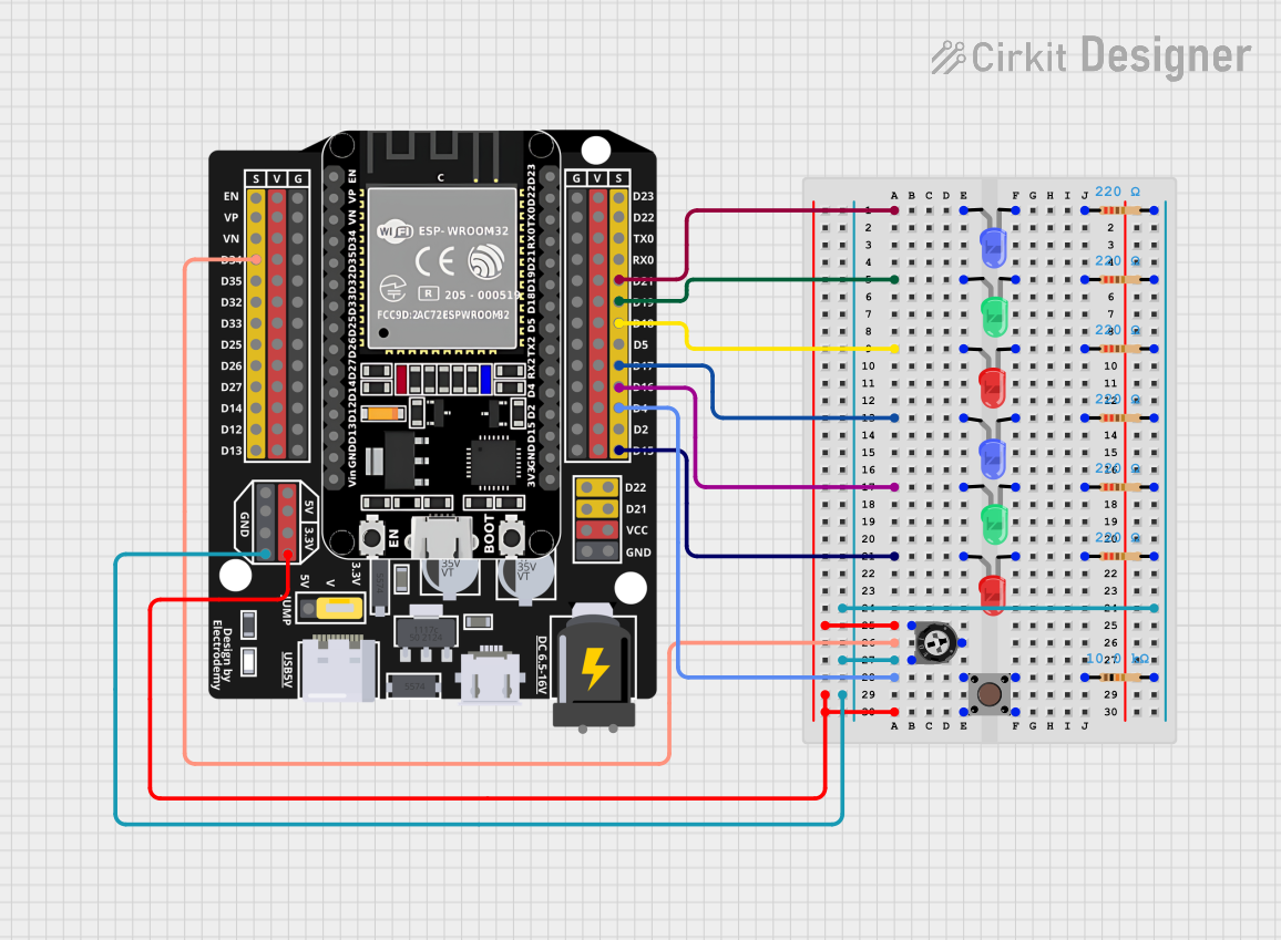
Circuit Documentation
Summary
This circuit is designed around the ESP32 Expansion Board, which serves as the central microcontroller unit. The circuit includes a variety of components such as LEDs, resistors, a trimmer potentiometer, and a pushbutton. The LEDs are controlled by the ESP32 and are used to indicate various statuses or events. The trimmer potentiometer is used to provide an adjustable voltage input to one of the ESP32's analog pins. The pushbutton is used to trigger an input on a digital pin of the ESP32. The resistors are used to limit current to the LEDs and to provide pull-down functionality for the pushbutton.
Component List
ESP32 - Expansion Board
- Description: A microcontroller board based on the ESP32 chip, featuring Wi-Fi and Bluetooth connectivity.
- Pins:
+,-,EN,VP,VN,D34,D32,D33,D25,D26,D27,D14,D12,D13,D23,D22,TX0,RX0,D21,D19,D18,D5,D17,D16,D4,D2,D15,VCC,G,5V,3.3V,V.
Resistor (220 Ohms)
- Description: A passive two-terminal electrical component that implements electrical resistance as a circuit element.
- Resistance: 220 Ohms.
Trimmer Potentiometer (10k Ohms)
- Description: A three-terminal resistor with a continuously adjustable tapping point controlled by rotation of a shaft or knob.
- Resistance: 10k Ohms.
Pushbutton
- Description: A simple switch mechanism for controlling some aspect of a machine or a process.
- Pins:
Pin 3 (out),Pin 4 (out),Pin 1 (in),Pin 2 (in).
LED: Two Pin (Red, Green, Blue)
- Description: Light Emitting Diodes of different colors used as indicators.
- Pins:
cathode,anode.
Wiring Details
ESP32 - Expansion Board
D21connected to anode of blue LED.D19connected to anode of green LED.D18connected to anode of red LED.D17connected to anode of another blue LED.D16connected to anode of another green LED.D15connected to anode of another red LED.3.3Vconnected to leg1 of trimmer potentiometer and Pin 1 (in) of pushbutton.D34connected to wiper of trimmer potentiometer.Gconnected to leg2 of trimmer potentiometer and pin2 of all resistors.D4connected to Pin 3 (out) of pushbutton.
Resistor (220 Ohms)
- One end (pin1) connected to cathode of corresponding LED.
- Other end (pin2) connected to ground (
G) of ESP32 Expansion Board.
Trimmer Potentiometer (10k Ohms)
leg1connected to3.3Vof ESP32 Expansion Board.wiperconnected toD34of ESP32 Expansion Board.leg2connected to ground (G) of ESP32 Expansion Board through resistors.
Pushbutton
Pin 1 (in)connected to3.3Vof ESP32 Expansion Board.Pin 3 (out)connected toD4of ESP32 Expansion Board.Pin 4 (out)connected to one end of a 10k Ohm resistor, other end of resistor connected to ground (G).
LED: Two Pin (Red, Green, Blue)
anodeconnected to corresponding digital pin (D21,D19,D18,D17,D16,D15) of ESP32 Expansion Board.cathodeconnected to one end of a 220 Ohm resistor, other end of resistor connected to ground (G).
Documented Code
No code has been provided for the microcontrollers in the circuit. The documentation of the code would typically include descriptions of the functionality implemented, such as LED control logic, button press detection, and analog input reading from the potentiometer. It would also include the actual source code with comments explaining the purpose of each section of the code. Since no code is available, this section remains empty.