Environmental Sensing and Data Logging System with GPS and Wi-Fi/LoRa Connectivity
Circuit Documentation
Summary
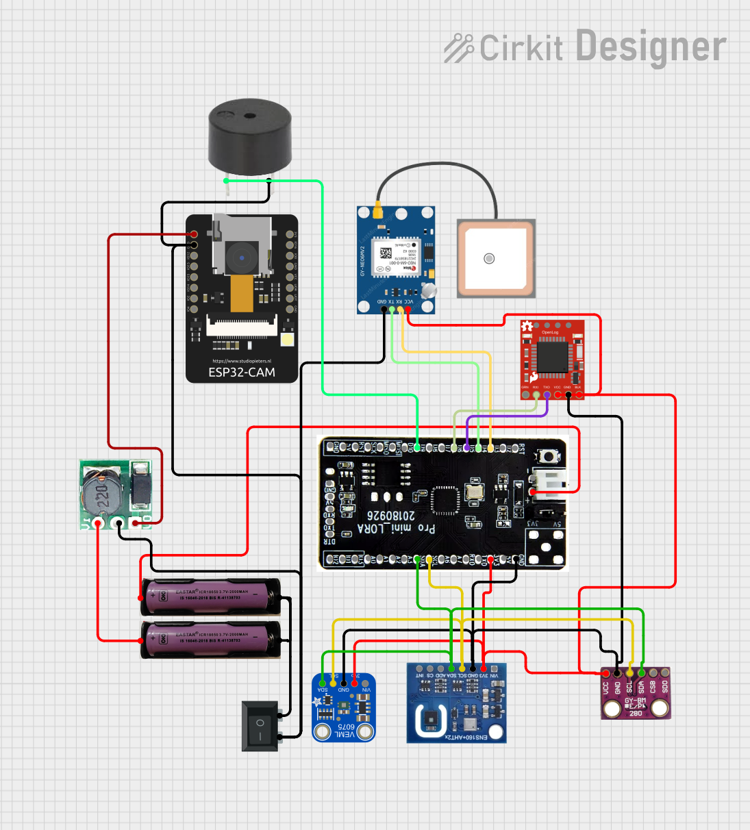
This circuit is designed to interface various sensors and modules with a T-Deer Pro Mini LoRa Atmega328P microcontroller. It includes power management components, environmental sensors, a GPS module, data logging capability, and a communication interface. The circuit is powered by two 3.7V batteries, with a step-up boost converter to provide 5V to the ESP32-CAM module. A rocker switch controls the power flow to the circuit. The sensors and modules communicate with the microcontroller via I2C and serial connections. Additionally, there is a buzzer for audio signaling.
Component List
Power Sources
- 3.7V Battery: Provides power to the circuit.
- Step Up Boost 3V-5V: Boosts the voltage from 3.7V to 5V for components requiring higher voltage.
Sensors
- BMP280: A sensor for measuring temperature, pressure, and altitude.
- Adafruit VEML6075 UV Sensor Breakout: Measures UVA and UVB light.
- ENS160+AHT21: A sensor module for air quality and temperature/humidity sensing.
- GPS NEO 6M: A GPS module for location tracking.
Data Logging and Communication
- SparkFun OpenLog: An open-source data logger that records serial data to a microSD card.
- ESP32-CAM: A small camera module with Wi-Fi capabilities.
Control and Indication
- Rocker Switch (SPST): A single-pole single-throw switch to control the power to the circuit.
- Buzzer: Provides audible feedback or alerts.
Microcontroller
- T-Deer Pro Mini LoRa Atmega328P: The main microcontroller board that manages sensor data and communications.
Wiring Details
Power Management
3.7V Battery
+to T-Deer Pro Mini LoRa Atmega328PJST +-to Rocker Switch1
Step Up Boost 3V-5V
Vito 3.7V Battery+GNDto Rocker Switch2Voto ESP32-CAM5V
Sensors
BMP280
SDAto I2C Bus (shared with other I2C devices)SCLto I2C Bus (shared with other I2C devices)GNDto common groundVCCto 3.3V power rail
Adafruit VEML6075 UV Sensor Breakout
SDAto I2C Bus (shared with other I2C devices)SCLto I2C Bus (shared with other I2C devices)GNDto common ground3.3Vto 3.3V power rail
ENS160+AHT21
SDAto I2C Bus (shared with other I2C devices)SCLto I2C Bus (shared with other I2C devices)GNDto common ground3V3to 3.3V power rail
GPS NEO 6M
VCCto common ground (possibly a mistake in the net list)RXto T-Deer Pro Mini LoRa Atmega328PD3TXto T-Deer Pro Mini LoRa Atmega328PD4GNDto common ground
Data Logging and Communication
SparkFun OpenLog
RXIto T-Deer Pro Mini LoRa Atmega328PD6TXOto T-Deer Pro Mini LoRa Atmega328PD5GNDto GPS NEO 6MVCC(possibly a mistake in the net list)VCCto 3.3V power rail
ESP32-CAM
GNDto common ground5Vto Step Up Boost 3V-5VVo
Control and Indication
Rocker Switch (SPST)
1to 3.7V Battery-2to common ground
Buzzer
PINto T-Deer Pro Mini LoRa Atmega328PD9GNDto common ground
Documented Code
There is no code provided for the microcontrollers in the circuit. The code would typically include initialization and configuration of the I2C bus, serial communication setup, sensor data acquisition, data logging routines, and any control logic for the buzzer or other outputs.
Please ensure that the wiring details are double-checked, as there may be errors in the net list provided, particularly with the common ground connections.