Cirkit Designer
Your all-in-one circuit design IDE
Home /
Project Documentation
Arduino UNO-Based IR Sensor Alarm System with LED Indicators and Buzzer
Circuit Documentation
Summary
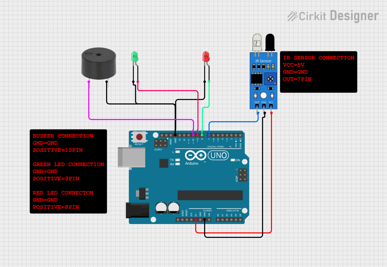
This circuit involves an Arduino UNO microcontroller interfacing with an IR sensor, a red LED, a green LED, and a buzzer. The IR sensor detects an object and triggers the LEDs and buzzer accordingly. The Arduino UNO serves as the central control unit, processing the sensor input and controlling the output devices.
Component List
Arduino UNO
- Description: A microcontroller board based on the ATmega328P.
- Pins: UNUSED, IOREF, Reset, 3.3V, 5V, GND, Vin, A0, A1, A2, A3, A4, A5, SCL, SDA, AREF, D13, D12, D11, D10, D9, D8, D7, D6, D5, D4, D3, D2, D1, D0
LED: Two Pin (red)
- Description: A red LED with two pins: anode and cathode.
- Pins: cathode, anode
LED: Two Pin (green)
- Description: A green LED with two pins: anode and cathode.
- Pins: cathode, anode
Buzzer
- Description: A simple buzzer with two pins: PIN and GND.
- Pins: PIN, GND
IR Sensor
- Description: An infrared sensor with three pins: out, gnd, and vcc.
- Pins: out, gnd, vcc
Wiring Details
Arduino UNO
- 5V: Connected to the vcc pin of the IR sensor.
- GND: Connected to the gnd pin of the IR sensor, the cathode pin of the red LED, the cathode pin of the green LED, and the GND pin of the buzzer.
- D10: Connected to the PIN of the buzzer.
- D9: Connected to the anode of the green LED.
- D8: Connected to the anode of the red LED.
- D7: Connected to the out pin of the IR sensor.
LED: Two Pin (red)
- cathode: Connected to the GND pin of the Arduino UNO.
- anode: Connected to the D8 pin of the Arduino UNO.
LED: Two Pin (green)
- cathode: Connected to the GND pin of the Arduino UNO.
- anode: Connected to the D9 pin of the Arduino UNO.
Buzzer
- PIN: Connected to the D10 pin of the Arduino UNO.
- GND: Connected to the GND pin of the Arduino UNO.
IR Sensor
- vcc: Connected to the 5V pin of the Arduino UNO.
- gnd: Connected to the GND pin of the Arduino UNO.
- out: Connected to the D7 pin of the Arduino UNO.
Code Documentation
Arduino UNO Code
void setup() {
  // put your setup code here, to run once:

}

void loop() {
  // put your main code here, to run repeatedly:

}
This code is a basic template for the Arduino UNO. The setup() function is where you initialize your components and settings, and the loop() function is where the main logic of your program runs repeatedly.
Additional Documentation
This section is reserved for any additional documentation or notes that may be required for understanding the circuit or the code.