Cirkit Designer
Your all-in-one circuit design IDE
Home /
Project Documentation
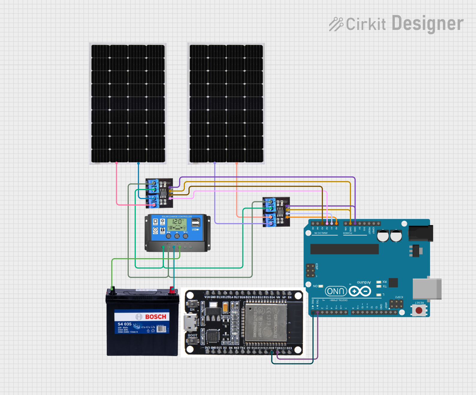
Solar Panel Monitoring System with Arduino and ESP32
Circuit Documentation
Summary
This circuit is designed to monitor the current and voltage of two solar panels using MAX471 current sensors and an Arduino UNO. The solar panels are connected to a solar charge controller, which in turn is connected to a 12V 200Ah battery. An ESP32 microcontroller is also included in the circuit for additional functionality.
Component List
Solar Panel
- Description: Converts sunlight into electrical energy.
- Pins: +, -
MAX471
- Description: Current sensor used to measure the current flowing through the solar panels.
- Pins: Vin, GND, Vout, AT, VT
Solar Charge Controller
- Description: Manages the charging of the battery from the solar panels and provides regulated power to the load.
- Pins: Solar Cell +, Solar Cell -, Battery +, Battery -, Load +, Load -
Arduino UNO
- Description: Microcontroller used to read sensor data and communicate with other components.
- Pins: UNUSED, IOREF, Reset, 3.3V, 5V, GND, Vin, A0, A1, A2, A3, A4, A5, SCL, SDA, AREF, D13, D12, D11, D10, D9, D8, D7, D6, D5, D4, D3, D2, D1, D0
12V 200Ah Battery
- Description: Stores electrical energy for use when solar power is not available.
- Pins: GND, 12V
ESP32
- Description: Microcontroller used for additional processing and communication tasks.
- Pins: EN, VP, VN, D34, D35, D32, D33, D25, D26, D27, D14, D12, D13, GND, VIN, 3V3, D15, D2, D4, RX2, TX2, D5, D18, D19, D21, RX0, TX0, D22, D23, BOOT
Wiring Details
Solar Panel 1
- Pin + connected to MAX471 Vin
- Pin - connected to MAX471 GND
Solar Panel 2
- Pin + connected to MAX471 Vin
- Pin - connected to MAX471 GND
MAX471 (for Solar Panel 1)
- Pin Vin connected to Solar Panel 1 +
- Pin GND connected to Solar Panel 1 -
- Pin Vout connected to Solar Charge Controller Solar Cell +
- Pin GND connected to Solar Charge Controller Solar Cell -
- Pin AT connected to Arduino UNO A0
- Pin VT connected to Arduino UNO A1
MAX471 (for Solar Panel 2)
- Pin Vin connected to Solar Panel 2 +
- Pin GND connected to Solar Panel 2 -
- Pin Vout connected to Solar Charge Controller Solar Cell +
- Pin GND connected to Solar Charge Controller Solar Cell -
- Pin AT connected to Arduino UNO A2
- Pin VT connected to Arduino UNO A3
Solar Charge Controller
- Pin Solar Cell + connected to MAX471 Vout
- Pin Solar Cell - connected to MAX471 GND
- Pin Battery + connected to 12V 200Ah Battery 12V
- Pin Battery - connected to 12V 200Ah Battery GND
Arduino UNO
- Pin GND connected to MAX471 GND
- Pin A0 connected to MAX471 AT (for Solar Panel 1)
- Pin A1 connected to MAX471 VT (for Solar Panel 1)
- Pin A2 connected to MAX471 AT (for Solar Panel 2)
- Pin A3 connected to MAX471 VT (for Solar Panel 2)
- Pin D1 connected to ESP32 TX0
- Pin D0 connected to ESP32 RX0
12V 200Ah Battery
- Pin 12V connected to Solar Charge Controller Battery +
- Pin GND connected to Solar Charge Controller Battery -
ESP32
- Pin TX0 connected to Arduino UNO D1
- Pin RX0 connected to Arduino UNO D0
Documented Code
Arduino UNO Code
// Pin analog untuk sensor MAX471
const int AT_PIN1 = A0; // Pin AT untuk sensor Panel 1
const int VT_PIN1 = A1; // Pin VT untuk sensor Panel 1
const int AT_PIN2 = A2; // Pin AT untuk sensor Panel 2
const int VT_PIN2 = A3; // Pin VT untuk sensor Panel 2

void setup() {
  Serial.begin(9600); // Inisialisasi komunikasi serial
}

void loop() {
  // Membaca data arus dan tegangan dari Panel 1
  int atValue1 = analogRead(AT_PIN1);
  float current1 = (atValue1 / 1024.0) * 5.0 / 0.1; // 1V = 1A, 0.1V = 0.1A (skala 0.1V/A)

  int vtValue1 = analogRead(VT_PIN1);
  float voltage1 = (vtValue1 / 1024.0) * 5.0; // Tegangan analog 0-5V

  // Membaca data arus dan tegangan dari Panel 2
  int atValue2 = analogRead(AT_PIN2);
  float current2 = (atValue2 / 1024.0) * 5.0 / 0.1; // 1V = 1A, 0.1V = 0.1A (skala 0.1V/A)

  int vtValue2 = analogRead(VT_PIN2);
  float voltage2 = (vtValue2 / 1024.0) * 5.0; // Tegangan analog 0-5V

  // Mengirim data ke Serial Monitor
  Serial.print("Panel1_Current: ");
  Serial.print(current1);
  Serial.print(" A, ");
  Serial.print("Panel1_Voltage: ");
  Serial.print(voltage1);
  Serial.println(" V");

  Serial.print("Panel2_Current: ");
  Serial.print(current2);
  Serial.print(" A, ");
  Serial.print("Panel2_Voltage: ");
  Serial.print(voltage2);
  Serial.println(" V");

  delay(1000); // Delay 1 detik untuk pembacaan berikutnya
}
ESP32 Code
void setup() {
  // put your setup code here, to run once:

}

void loop() {
  // put your main code here, to run repeatedly:

}
This documentation provides a comprehensive overview of the circuit, including a summary, component list, wiring details, and documented code for the microcontrollers.