
Arduino UNO-Based Smart Light Controller with PID and LCD Display
View and Edit Project In Cirkit Designer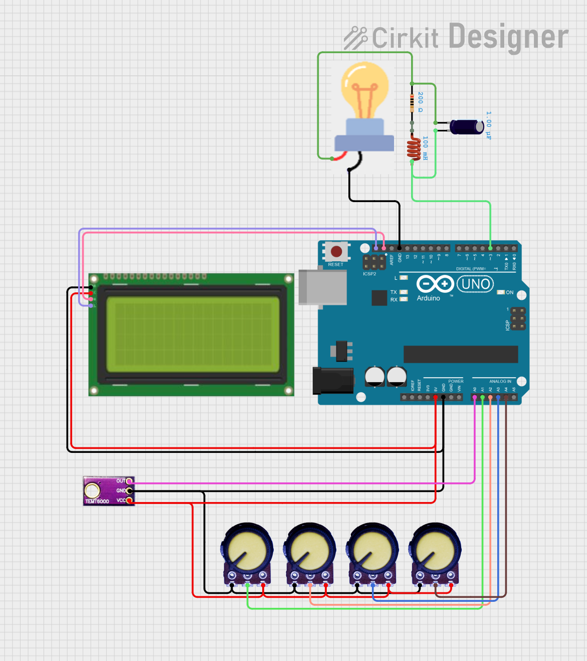
Circuit Documentation
Summary
This circuit is designed to control the brightness of an LED based on ambient light intensity using a PID controller. The system includes an Arduino UNO microcontroller, multiple potentiometers for tuning PID parameters, an ambient light sensor, an LCD display for real-time feedback, and additional passive components like resistors, capacitors, and inductors.
Component List
Arduino UNO
- Description: Microcontroller board based on the ATmega328P.
- Pins: UNUSED, IOREF, Reset, 3.3V, 5V, GND, Vin, A0, A1, A2, A3, A4, A5, SCL, SDA, AREF, D13, D12, D11, D10, D9, D8, D7, D6, D5, D4, D3, D2, D1, D0
Potentiometer
- Description: Variable resistor used for adjusting PID parameters.
- Pins: GND, Output, VCC
Ambient Light Sensor
- Description: Sensor to measure ambient light intensity.
- Pins: GND, OUT, VCC
LCD 20x4 I2C
- Description: 20x4 character LCD display with I2C interface.
- Pins: GND, 5V, SCA, SCL
Electrolytic Capacitor
- Description: Capacitor used for filtering.
- Pins: -, +
- Properties: Capacitance: 0.000001 Farads
Inductor
- Description: Inductor used in the circuit.
- Pins: pin 0, pin 1
- Properties: Inductance: 0.1 Henrys
Resistor
- Description: Resistor used in the circuit.
- Pins: pin1, pin2
- Properties: Resistance: 200 Ohms
Bulb
- Description: Bulb used as an indicator.
- Pins: GND, power
Wiring Details
Arduino UNO
5V connected to:
- Potentiometer (VCC)
- Potentiometer (VCC)
- Ambient Light Sensor (VCC)
- LCD 20x4 I2C (5V)
- Potentiometer (VCC)
- Potentiometer (VCC)
GND connected to:
- Potentiometer (GND)
- Potentiometer (GND)
- Ambient Light Sensor (GND)
- LCD 20x4 I2C (GND)
- Potentiometer (GND)
- Potentiometer (GND)
- Bulb (GND)
A0 connected to:
- Ambient Light Sensor (OUT)
A1 connected to:
- Potentiometer (Output)
A2 connected to:
- Potentiometer (Output)
A3 connected to:
- Potentiometer (Output)
A4 connected to:
- Potentiometer (Output)
SCL connected to:
- LCD 20x4 I2C (SCL)
SDA connected to:
- LCD 20x4 I2C (SCA)
D3 connected to:
- Electrolytic Capacitor (+)
- Inductor (pin 1)
Potentiometer
VCC connected to:
- Arduino UNO (5V)
GND connected to:
- Arduino UNO (GND)
Output connected to:
- Arduino UNO (A1)
- Arduino UNO (A2)
- Arduino UNO (A3)
- Arduino UNO (A4)
Ambient Light Sensor
VCC connected to:
- Arduino UNO (5V)
GND connected to:
- Arduino UNO (GND)
OUT connected to:
- Arduino UNO (A0)
LCD 20x4 I2C
5V connected to:
- Arduino UNO (5V)
GND connected to:
- Arduino UNO (GND)
SCA connected to:
- Arduino UNO (SDA)
SCL connected to:
- Arduino UNO (SCL)
Electrolytic Capacitor
+ connected to:
- Arduino UNO (D3)
- Inductor (pin 1)
- connected to:
- Bulb (power)
- Resistor (pin1)
Inductor
pin 0 connected to:
- Resistor (pin2)
pin 1 connected to:
- Electrolytic Capacitor (+)
- Arduino UNO (D3)
Resistor
pin1 connected to:
- Electrolytic Capacitor (-)
pin2 connected to:
- Inductor (pin 0)
Bulb
GND connected to:
- Arduino UNO (GND)
power connected to:
- Electrolytic Capacitor (-)
Code Documentation
#include <PID_v1.h>
#include <Wire.h>
#include <LiquidCrystal_I2C.h>

// Initialize the LCD with I2C address 0x27 and size 20x4
LiquidCrystal_I2C lcd(0x27, 20, 4);

const int MAX_DUTY_CYCLE = 255; // Max duty cycle for 8-bit resolution

// PID parameters and variables
double Setpoint, Input, Output;
double kp, ki, kd;
PID myPID(&Input, &Output, &Setpoint, kp, ki, kd, DIRECT);

// Pin definitions
const int temt6000Pin = A0; // Analog pin for TEMT6000 sensor
const int ledPin = 3;       // PWM pin for LED control via MOSFET
const int kpPin = A1;       // Analog pin for potentiometer to adjust Kp
const int kiPin = A2;       // Analog pin for potentiometer to adjust Ki
const int kdPin = A3;       // Analog pin for potentiometer to adjust Kd

// Fading parameters
int targetBrightness = 0;
int currentBrightness = 0;
const int fadeAmount = 1; // Fade amount for each step
const int fadeDelay = 30; // Delay in milliseconds for each fade step

//lux tuning parameter
const int LUX_TUNING = 200;

void setup() {
  Serial.begin(115200);

  // Initialize the LCD
  lcd.init();
  lcd.backlight();

  // Set initial PID parameters
  Setpoint = 0; // Desired light intensity in lux

  myPID.SetMode(AUTOMATIC);
  myPID.SetSampleTime(100); // Sample time in milliseconds

  pinMode(ledPin, OUTPUT); // Set LED pin as output
}

void loop() {
  // Read the light intensity from the TEMT6000 sensor
  int light_value = analogRead(temt6000Pin);
  float volts = light_value * 3.3 / 1023.0; // Arduino has 10-bit ADC resolution and 3.3V reference voltage
  float amps = volts / 10000.0; // across 10,000 Ohms
  float microamps = amps * 1000000;
  float lux = microamps * 2.0;
  Input = lux;

  // Read and scale potentiometer values to 0-10 range for PID parameters
  kp = analogRead(kpPin) * (10.0 / 1023.0);
  ki = analogRead(kiPin) * (10.0 / 1023.0);
  kd = analogRead(kdPin) * (10.0 / 1023.0);
  myPID.SetTunings(kp, ki, kd);

  // Compute the PID output
  myPID.Compute();

  // Set the LED brightness based on the lux value directly (scale 0-255)
  targetBrightness = map(lux, 0, LUX_TUNING, MAX_DUTY_CYCLE, 0);
  targetBrightness = constrain(targetBrightness, 0, MAX_DUTY_CYCLE);

  // Smoothly adjust currentBrightness towards targetBrightness
  if (currentBrightness < targetBrightness) {
    currentBrightness = min(currentBrightness + fadeAmount, targetBrightness);
  } else if (currentBrightness > targetBrightness) {
    currentBrightness = max(currentBrightness - fadeAmount, targetBrightness);
  }

  // Set the LED brightness
  analogWrite(ledPin, currentBrightness);

  // Display PID parameters and light intensity on the LCD
  lcd.setCursor(0, 0);
  lcd.print("P=");
  lcd.print(kp, 2);
  lcd.print(" I=");
  lcd.print(ki, 2);

  lcd.setCursor(0, 1);
  lcd.print("D=");
  lcd.print(kd, 2);

  lcd.setCursor(0, 2);
  lcd.print("Light Intensity:");
  lcd.setCursor(0