ESP32-Based Smart Home Automation System with Temperature and Gas Monitoring
Circuit Documentation
Summary
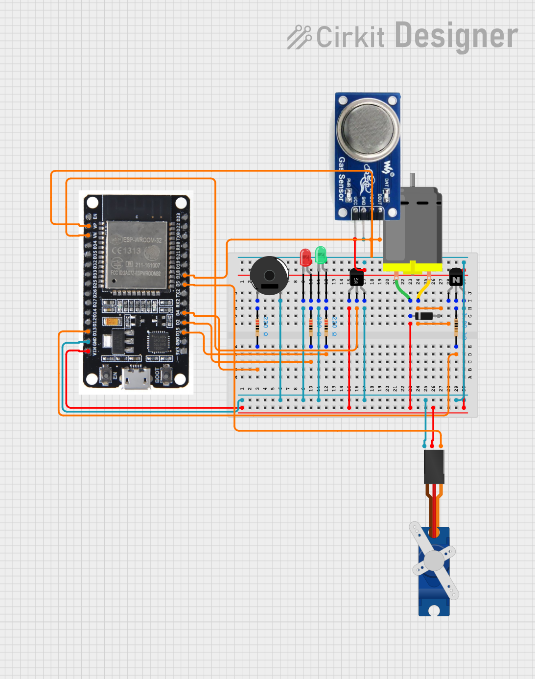
This circuit involves an ESP32 microcontroller interfacing with various components including a DC motor, temperature sensor (LM35), NPN transistor, LEDs, resistors, a piezo buzzer, a servo motor, and an MQ 135 gas sensor. The circuit is designed to control and monitor these components, with the ESP32 serving as the central control unit.
Component List
DC Motor
- Description: A motor that converts electrical energy into mechanical energy.
- Pins: pin 1, pin 2
Temperature Sensor (LM35)
- Description: A sensor that provides an analog output proportional to the temperature.
- Pins: +Vs, Vout, GND
NPN Transistor (CBE)
- Description: A transistor used for switching and amplification.
- Pins: collector, base, emitter
LED: Two Pin (red)
- Description: A red light-emitting diode.
- Pins: cathode, anode
LED: Two Pin (green)
- Description: A green light-emitting diode.
- Pins: cathode, anode
Resistor (220 Ohms)
- Description: A resistor with a resistance of 220 Ohms.
- Pins: pin1, pin2
Resistor (1000 Ohms)
- Description: A resistor with a resistance of 1000 Ohms.
- Pins: pin1, pin2
Piezo Buzzer
- Description: A device that produces sound when an electric signal is applied.
- Pins: pin 1, pin 2
Diode
- Description: A component that allows current to flow in one direction only.
- Pins: cathode, anode
MQ 135
- Description: A gas sensor that detects air quality.
- Pins: D OUT, A OUT, GND, VCC
Tower Pro SG90 Servo
- Description: A small servo motor used for precise control of angular position.
- Pins: Signal, +5V, GND
ESP32
- Description: A microcontroller with integrated Wi-Fi and Bluetooth capabilities.
- Pins: EN, VP, VN, D34, D35, D32, D33, D25, D26, D27, D14, D12, D13, GND, VIN, 3V3, D15, D2, D4, RX2, TX2, D5, D18, D19, D21, RX0, TX0, D22, D23, BOOT
Wiring Details
DC Motor
pin 1 is connected to:
- Temperature Sensor (LM35) +Vs
- Diode cathode
- ESP32 VIN
- Tower Pro SG90 Servo +5V
- MQ 135 VCC
pin 2 is connected to:
- NPN Transistor (CBE) collector
Temperature Sensor (LM35)
+Vs is connected to:
- DC Motor pin 1
Vout is connected to:
- ESP32 VN
GND is connected to:
- Piezo Buzzer pin 2
- LED: Two Pin (red) cathode
- LED: Two Pin (green) cathode
- NPN Transistor (CBE) emitter
- ESP32 GND
- Tower Pro SG90 Servo GND
- MQ 135 GND
NPN Transistor (CBE)
collector is connected to:
- DC Motor pin 2
base is connected to:
- Resistor (1000 Ohms) pin1
emitter is connected to:
- Temperature Sensor (LM35) GND
LED: Two Pin (red)
cathode is connected to:
- Piezo Buzzer pin 2
- LED: Two Pin (green) cathode
- Temperature Sensor (LM35) GND
- NPN Transistor (CBE) emitter
- ESP32 GND
- Tower Pro SG90 Servo GND
- MQ 135 GND
anode is connected to:
- Resistor (220 Ohms) pin1
LED: Two Pin (green)
cathode is connected to:
- Piezo Buzzer pin 2
- LED: Two Pin (red) cathode
- Temperature Sensor (LM35) GND
- NPN Transistor (CBE) emitter
- ESP32 GND
- Tower Pro SG90 Servo GND
- MQ 135 GND
anode is connected to:
- Resistor (220 Ohms) pin1
Resistor (220 Ohms)
pin1 is connected to:
- LED: Two Pin (red) anode
pin2 is connected to:
- ESP32 D2
Resistor (1000 Ohms)
pin1 is connected to:
- NPN Transistor (CBE) base
pin2 is connected to:
- ESP32 D13
Piezo Buzzer
pin 1 is connected to:
- Resistor (220 Ohms) pin1
pin 2 is connected to:
- LED: Two Pin (red) cathode
- LED: Two Pin (green) cathode
- Temperature Sensor (LM35) GND
- NPN Transistor (CBE) emitter
- ESP32 GND
- Tower Pro SG90 Servo GND
- MQ 135 GND
Diode
cathode is connected to:
- DC Motor pin 1
anode is not connected to any other component.
MQ 135
D OUT is connected to:
- ESP32 D18
A OUT is connected to:
- ESP32 VP
GND is connected to:
- Piezo Buzzer pin 2
- LED: Two Pin (red) cathode
- LED: Two Pin (green) cathode
- Temperature Sensor (LM35) GND
- NPN Transistor (CBE) emitter
- ESP32 GND
- Tower Pro SG90 Servo GND
VCC is connected to:
- DC Motor pin 1
Tower Pro SG90 Servo
Signal is connected to:
- ESP32 D5
+5V is connected to:
- DC Motor pin 1
GND is connected to:
- Piezo Buzzer pin 2
- LED: Two Pin (red) cathode
- LED: Two Pin (green) cathode
- Temperature Sensor (LM35) GND
- NPN Transistor (CBE) emitter
- ESP32 GND
- MQ 135 GND
ESP32
D4 is connected to:
- Resistor (220 Ohms) pin2
D2 is connected to:
- Resistor (220 Ohms) pin2
D15 is connected to:
- Resistor (220 Ohms) pin2
VN is connected to:
- Temperature Sensor (LM35) Vout
VIN is connected to:
- DC Motor pin 1
GND is connected to:
- Piezo Buzzer pin 2
- LED: Two Pin (red) cathode
- LED: Two Pin (green) cathode
- Temperature Sensor (LM35) GND
- NPN Transistor (CBE) emitter
- Tower Pro SG90 Servo GND
- MQ 135 GND
VP is connected to:
- MQ 135 A OUT
D5 is connected to:
- Tower Pro SG90 Servo Signal
D18 is connected to:
- MQ 135 D OUT
D13 is connected to:
- Resistor (1000 Ohms) pin2
Documented Code
ESP32 Code
void setup() {
  // put your setup code here, to run once:

}

void loop() {
  // put your main code here, to run repeatedly:

}
This code is a basic template for the ESP32 microcontroller. The setup function is where you initialize your components and configurations, and the loop function is where you place the code that needs to run continuously.