
ESP32-Based Automated Irrigation System with Soil Moisture and Water Level Sensors
View and Edit Project In Cirkit Designer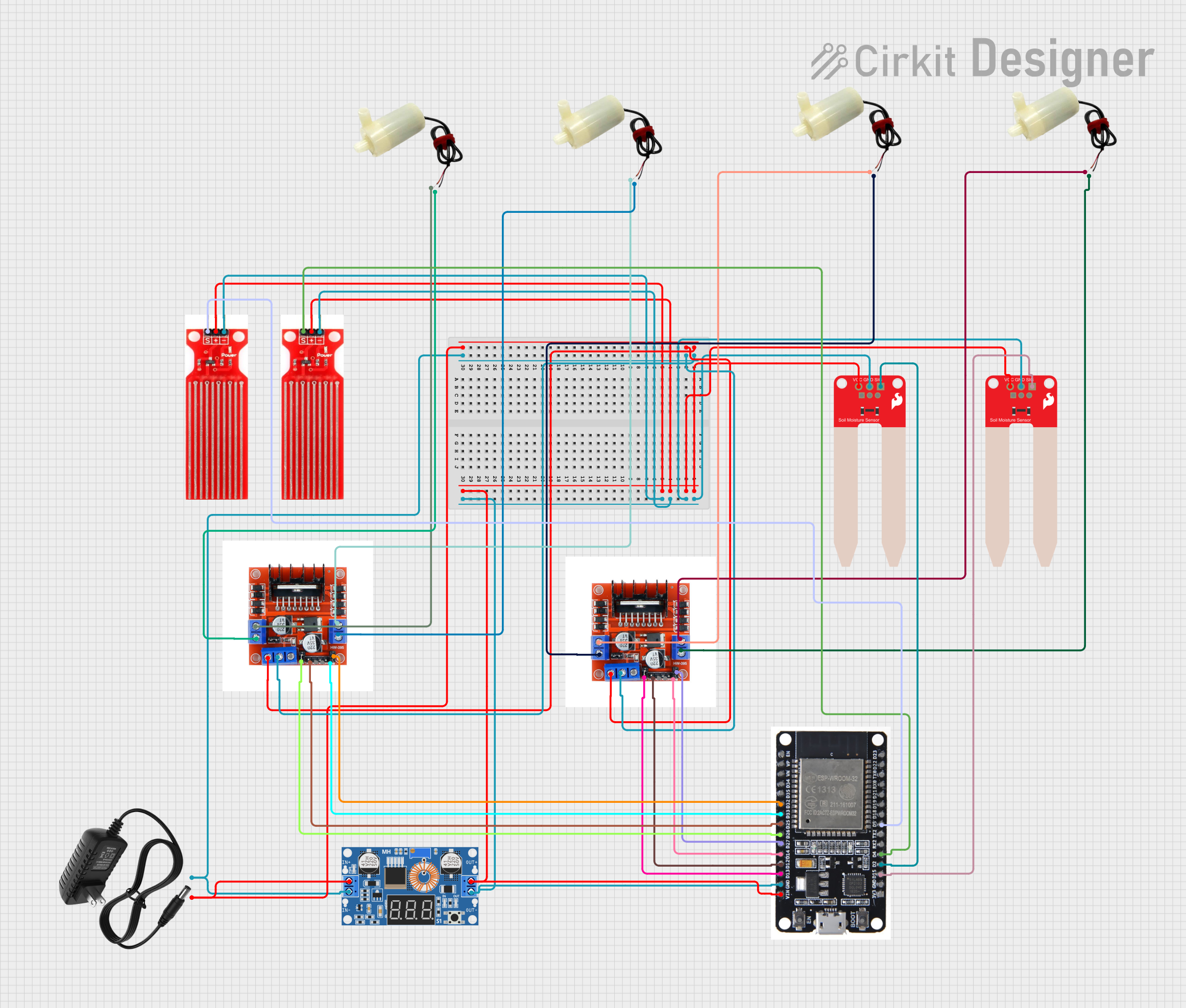
Circuit Documentation
Summary
This circuit is designed to control a system with two fields, each having a motor, a soil moisture sensor, and a water level sensor. The system monitors the soil moisture levels and water levels in each field. When a field is detected to be dry, the corresponding water pump is activated to balance the water levels.
Component List
5V Mini Water Pump
- Description: A small water pump used to irrigate the fields.
- Pins: Positive pin, Negative pin
SparkFun Soil Moisture Sensor
- Description: A sensor used to measure the moisture level in the soil.
- Pins: VCC, GND, SIG
XL4015 5A DC Buck Step-down
- Description: A DC-DC buck converter used to step down the voltage.
- Pins: Output +, Output -, Input +, Input -
L298N 2A Dual Motor Driver Module with PWM Control
- Description: A motor driver module used to control the water pumps.
- Pins: OUT1, OUT2, 12V, GND, 5V, OUT4, OUT3, ENA, IN1, IN2, IN3, ENB, IN4
Water Sensor
- Description: A sensor used to detect the water level.
- Pins: Signal, VCC, GND
ESP32
- Description: A microcontroller used to control the entire system.
- Pins: EN, VP, VN, D34, D35, D32, D33, D25, D26, D27, D14, D12, D13, GND, VIN, 3V3, D15, D2, D4, RX2, TX2, D5, D18, D19, D21, RX0, TX0, D22, D23, BOOT
12V Power Supply
- Description: A power supply providing 12V to the circuit.
- Pins: +, -
Wiring Details
5V Mini Water Pump
Positive pin connected to:
- OUT4 of L298N Motor Driver Module
- OUT1 of L298N Motor Driver Module
- OUT1 of L298N Motor Driver Module
- OUT4 of L298N Motor Driver Module
Negative pin connected to:
- OUT3 of L298N Motor Driver Module
- OUT2 of L298N Motor Driver Module
- OUT2 of L298N Motor Driver Module
- OUT3 of L298N Motor Driver Module
SparkFun Soil Moisture Sensor
VCC connected to:
- Output + of XL4015 DC Buck Step-down
- Output + of XL4015 DC Buck Step-down
GND connected to:
- Output - of XL4015 DC Buck Step-down
- Output - of XL4015 DC Buck Step-down
SIG connected to:
- D2 of ESP32
- D15 of ESP32
XL4015 5A DC Buck Step-down
Input + connected to:
- 12V of L298N Motor Driver Module
- 12V of L298N Motor Driver Module
-
- of 12V Power Supply
Input - connected to:
- GND of L298N Motor Driver Module
- GND of L298N Motor Driver Module
-
- of 12V Power Supply
Output + connected to:
- VCC of SparkFun Soil Moisture Sensor
- VCC of SparkFun Soil Moisture Sensor
- VCC of Water Sensor
- VCC of Water Sensor
- VIN of ESP32
Output - connected to:
- GND of SparkFun Soil Moisture Sensor
- GND of SparkFun Soil Moisture Sensor
- GND of Water Sensor
- GND of Water Sensor
- GND of ESP32
L298N 2A Dual Motor Driver Module with PWM Control
12V connected to:
- Input + of XL4015 DC Buck Step-down
-
- of 12V Power Supply
GND connected to:
- Input - of XL4015 DC Buck Step-down
-
- of 12V Power Supply
OUT1 connected to:
- Positive pin of 5V Mini Water Pump
- Positive pin of 5V Mini Water Pump
OUT2 connected to:
- Negative pin of 5V Mini Water Pump
- Negative pin of 5V Mini Water Pump
OUT3 connected to:
- Negative pin of 5V Mini Water Pump
- Negative pin of 5V Mini Water Pump
OUT4 connected to:
- Positive pin of 5V Mini Water Pump
- Positive pin of 5V Mini Water Pump
ENA connected to:
- D26 of ESP32
- D13 of ESP32
ENB connected to:
- D32 of ESP32
- D27 of ESP32
IN1 connected to:
- D25 of ESP32
- D12 of ESP32
IN4 connected to:
- D33 of ESP32
- D14 of ESP32
Water Sensor
Signal connected to:
- D4 of ESP32
- D5 of ESP32
VCC connected to:
- Output + of XL4015 DC Buck Step-down
GND connected to:
- Output - of XL4015 DC Buck Step-down
ESP32
VIN connected to:
- Output + of XL4015 DC Buck Step-down
GND connected to:
- Output - of XL4015 DC Buck Step-down
D2 connected to:
- SIG of SparkFun Soil Moisture Sensor
D15 connected to:
- SIG of SparkFun Soil Moisture Sensor
D4 connected to:
- Signal of Water Sensor
D5 connected to:
- Signal of Water Sensor
D25 connected to:
- IN1 of L298N Motor Driver Module
D26 connected to:
- ENA of L298N Motor Driver Module
D27 connected to:
- ENB of L298N Motor Driver Module
D32 connected to:
- ENB of L298N Motor Driver Module
D33 connected to:
- IN4 of L298N Motor Driver Module
D12 connected to:
- IN1 of L298N Motor Driver Module
D13 connected to:
- ENA of L298N Motor Driver Module
D14 connected to:
- IN4 of L298N Motor Driver Module
Code Documentation
/*
 * This Arduino Sketch controls a system with two fields, each having a motor,
 * a soil moisture sensor, and a water level sensor. When a field is detected
 * to be dry, the corresponding water pump is activated to balance the water
 * levels.
 */

// Pin definitions
const int soilMoisturePin1 = 2;
const int soilMoisturePin2 = 15;
const int waterSensorPin1 = 4;
const int waterSensorPin2 = 5;
const int motorPin1 = 13;
const int motorPin2 = 27;
const int motorControlPin1A = 12;
const int motorControlPin1B = 14;
const int motorControlPin2A = 25;
const int motorControlPin2B = 33;

void setup() {
  // Initialize serial communication
  Serial.begin(9600);

  // Initialize pins
  pinMode(soilMoisturePin1, INPUT);
  pinMode(soilMoisturePin2, INPUT);
  pinMode(waterSensorPin1, INPUT);
  pinMode(waterSensorPin2, INPUT);
  pinMode(motorPin1, OUTPUT);
  pinMode(motorPin2, OUTPUT);
  pinMode(motorControlPin1A, OUTPUT);
  pinMode(motorControlPin1B, OUTPUT);
  pinMode(motorControlPin2A, OUTPUT);
  pinMode(motorControlPin2B, OUTPUT);
}

void loop() {
  // Read soil moisture levels
  int soilMoisture1 = analogRead(soilMoisturePin1);
  int soilMoisture2 = analogRead(soilMoisturePin2);

  // Read water levels
  int waterLevel1 = digitalRead(waterSensorPin1);
  int waterLevel2 = digitalRead(waterSensorPin2);

  // Check if field 1 is dry
  if (soilMoisture1 < 500) {
    // Activate motor 1 to balance water levels
    digitalWrite(motorPin1, HIGH);
    digitalWrite(motorControlPin1A, HIGH);
    digitalWrite(motorControlPin1B, LOW);
  } else {
    // Deactivate motor 1