
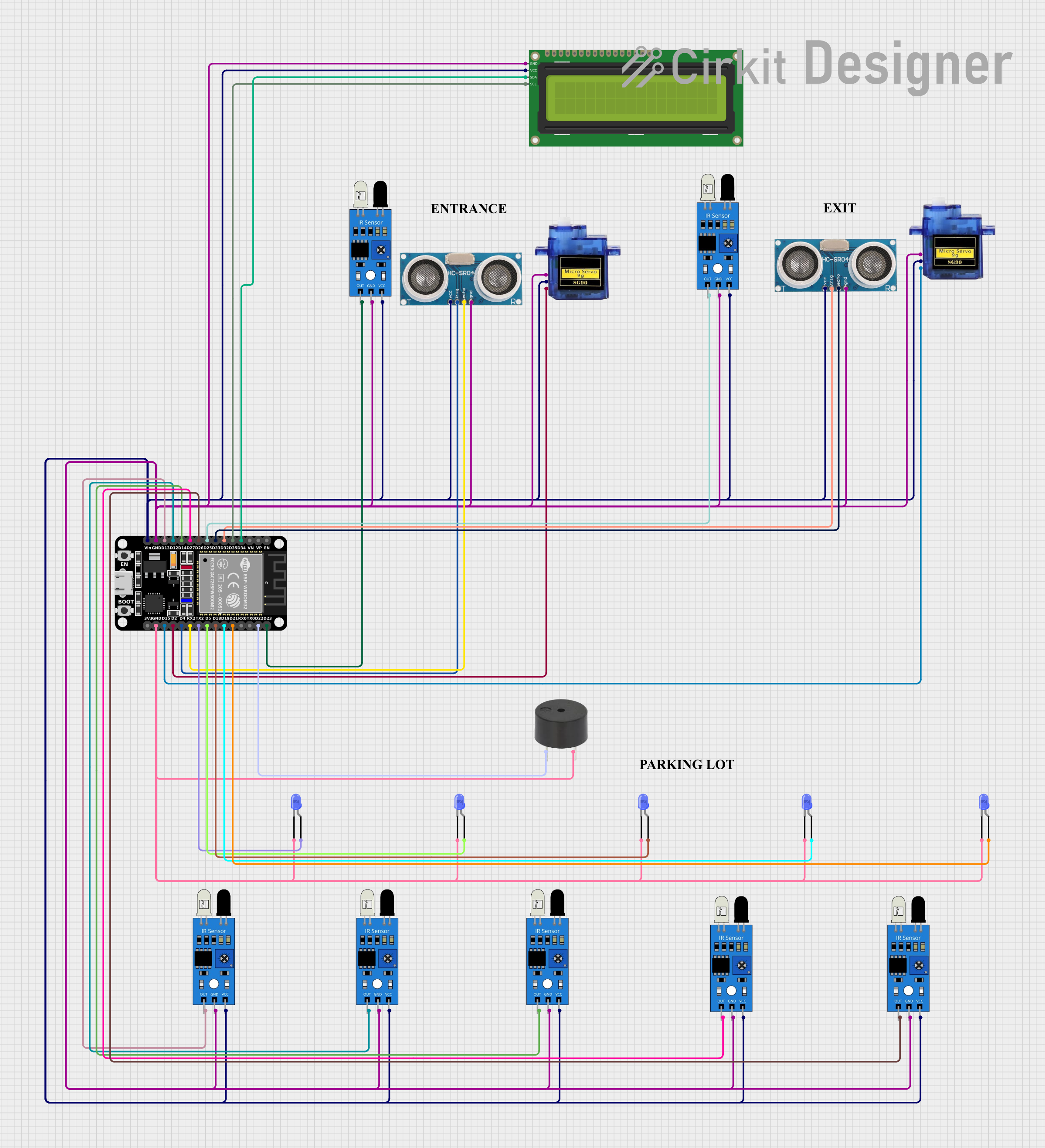
Circuit Documentation
Summary
This circuit integrates various sensors, actuators, and a display module with an ESP32 microcontroller. The primary components include an ESP32 (30 pin) microcontroller, multiple IR sensors, two ultrasonic sensors, two micro servos, a 16x2 I2C LCD, and several LEDs and a buzzer for output. The ESP32 serves as the central processing unit, interfacing with the IR and ultrasonic sensors to receive input signals. The micro servos are controlled via PWM signals, and the LEDs and buzzer provide visual and auditory feedback, respectively. The 16x2 I2C LCD displays relevant information. The circuit is designed for applications that require distance measurement, object detection, and feedback mechanisms.
Component List
ESP32 (30 pin)
- Microcontroller with WiFi and Bluetooth capabilities.
- 30 GPIO pins including analog inputs, UART, I2C, and PWM.
Micro servo 9G (x2)
- Small and lightweight servo motor.
- Controlled by PWM signal.
IR Sensor (x6)
- Infrared sensor for object detection.
- Outputs a digital signal when an object is detected.
Ultrasonic Sensor (x2)
- Sensor for measuring distance via ultrasonic waves.
- Consists of a trigger and echo pin.
16x2 I2C LCD
- Alphanumeric liquid crystal display.
- Communicates over I2C protocol.
LED: Two Pin (blue) (x5)
- Standard blue LED.
- Requires current limiting resistor.
Buzzer
- Emits an audible tone when powered.
Comment (x4)
- Placeholder for additional notes or labels (not an actual electronic component).
Wiring Details
ESP32 (30 pin)
D34connected to 16x2 I2C LCD SDAD35connected to 16x2 I2C LCD SCLD32connected to Ultrasonic Sensor TriggerD33connected to Ultrasonic Sensor EchoD25,D26,D27,D14,D12,D13connected to IR Sensor out pinsGNDconnected to common ground netVinconnected to common VCC netD23,D22,D21,D19,D18,D5,TX2connected to IR Sensor out pins or Buzzer PINRX2connected to Ultrasonic Sensor EchoD4connected to Ultrasonic Sensor TriggerD2,D15connected to Micro servo 9G PWM pins
Micro servo 9G
GNDconnected to common ground net+5Vconnected to common VCC netPWMconnected to ESP32 GPIO pinsD2andD15
IR Sensor
outconnected to various GPIO pins on the ESP32gndconnected to common ground netvccconnected to common VCC net
Ultrasonic Sensor
+VCCconnected to common VCC netTriggerconnected to ESP32 GPIO pinsD32andD4Echoconnected to ESP32 GPIO pinsD33andRX2GNDconnected to common ground net
16x2 I2C LCD
GNDconnected to common ground netVCCconnected to common VCC netSDAconnected to ESP32 GPIO pinD34SCLconnected to ESP32 GPIO pinD35
LED: Two Pin (blue)
cathodeconnected to common ground netanodeconnected to various GPIO pins on the ESP32
Buzzer
PINconnected to ESP32 GPIO pinD22GNDconnected to common ground net
Documented Code
No code has been provided for the microcontrollers in the circuit. The code would typically include initialization of the GPIO pins, setup for I2C communication, PWM signal generation for the servos, and logic for reading sensor inputs and driving the outputs (LEDs and buzzer). It would also handle the display output for the 16x2 I2C LCD.