
Arduino UNO Controlled RGB LED and Servo Motor System with Push Button Activation
View and Edit Project In Cirkit Designer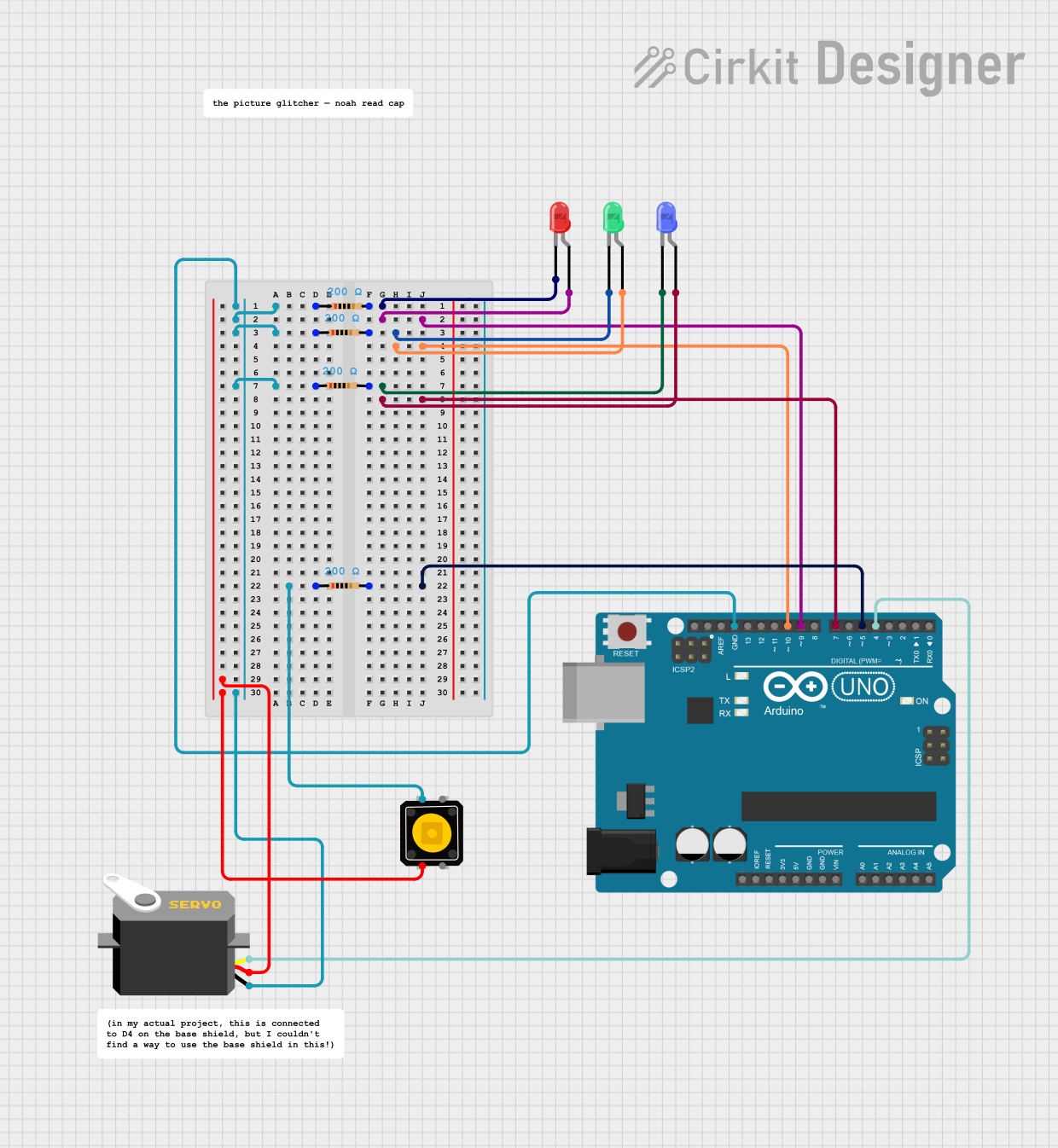
Circuit Documentation
Summary
This circuit involves an Arduino UNO microcontroller controlling three LEDs (red, green, and blue), a servo motor, and a momentary push button switch. The LEDs are connected through resistors to limit current, and the servo motor is controlled via a pulse pin. The push button switch is used to trigger actions in the circuit, such as lighting up the LEDs and moving the servo motor.
Component List
LED: Two Pin (red)
- Pins: cathode, anode
- Description: Red LED
LED: Two Pin (green)
- Pins: cathode, anode
- Description: Green LED
LED: Two Pin (blue)
- Pins: cathode, anode
- Description: Blue LED
Servo
- Pins: gnd, vcc, pulse
- Description: Servo motor
Resistor
- Pins: pin1, pin2
- Description: 200 Ohms resistor
Arduino UNO
- Pins: UNUSED, IOREF, Reset, 3.3V, 5V, GND, Vin, A0, A1, A2, A3, A4, A5, SCL, SDA, AREF, D13, D12, D11, D10, D9, D8, D7, D6, D5, D4, D3, D2, D1, D0
- Description: Microcontroller
Momentary Push Button Switch
- Pins: 1, 3, 2, 4
- Description: Push button switch
Wiring Details
LED: Two Pin (red)
- Cathode: Connected to pin2 of a 200 Ohms resistor
- Anode: Connected to D9 of Arduino UNO
LED: Two Pin (green)
- Cathode: Connected to pin2 of a 200 Ohms resistor
- Anode: Connected to D10 of Arduino UNO
LED: Two Pin (blue)
- Cathode: Connected to pin2 of a 200 Ohms resistor
- Anode: Connected to D7 of Arduino UNO
Servo
- Gnd: Connected to GND of Arduino UNO
- Vcc: Connected to pin2 of the momentary push button switch
- Pulse: Connected to D4 of Arduino UNO
Resistor (200 Ohms)
- Pin1: Connected to GND of Arduino UNO
- Pin2: Connected to cathode of the red LED
Resistor (200 Ohms)
- Pin1: Connected to GND of Arduino UNO
- Pin2: Connected to cathode of the green LED
Resistor (200 Ohms)
- Pin1: Connected to GND of Arduino UNO
- Pin2: Connected to cathode of the blue LED
Resistor (200 Ohms)
- Pin1: Connected to pin1 of the momentary push button switch
- Pin2: Connected to D5 of Arduino UNO
Arduino UNO
- GND: Connected to pin1 of three 200 Ohms resistors and gnd of the servo
- D9: Connected to anode of the red LED
- D10: Connected to anode of the green LED
- D7: Connected to anode of the blue LED
- D4: Connected to pulse of the servo
- D5: Connected to pin2 of a 200 Ohms resistor
Momentary Push Button Switch
- Pin1: Connected to pin1 of a 200 Ohms resistor
- Pin2: Connected to vcc of the servo
Code Documentation
#include <Servo.h>
#include <Wire.h>
#include <rgb_lcd.h> // Grove LCD library

rgb_lcd lcd; // Create an LCD object

Servo myservo; // Create Servo object to control a servo
int RED1 = 9;
int GREEN1 = 10;
int BLUE1 = 7;
int VIB = 6;
int SWITCH = 5; // Switch connected to pin 5
int VAL;
int pos = 0; // Variable to store the servo position
// Servo in to D4
// LCD (if used?!) in to 12C, the one below D8

//VIB MOTOR:
// IN - 6
//VCC - 5V BUT only if not using the swithc as only on 5V output -- so maybe no can do
//GND - GND

bool switchState = false; // Current state of the switch (pressed or not)
bool lastSwitchState = false; // Previous state of the switch (to detect change)
bool actionRunning = false; // To track if the action is running

void setup() {
  pinMode(RED1, OUTPUT);
  pinMode(GREEN1, OUTPUT);
  pinMode(BLUE1, OUTPUT);
  pinMode(VIB, OUTPUT);
  pinMode(SWITCH, INPUT); // Switch as input
  myservo.attach(4);
  lcd.begin(16, 2); // Initialise LCD
  lcd.clear();
}

void loop() {
  // Read the switch state
  switchState = digitalRead(SWITCH);

  // Check for a change in switch state (from LOW to HIGH or HIGH to LOW)
  if (switchState != lastSwitchState) {
    if (switchState == LOW) {
      // Switch pressed: Start the action
      actionRunning = true;
      //lcd.clear();
      //lcd.setCursor(0, 0);
      //lcd.print("Action Started");
      digitalWrite(VIB, HIGH);
      digitalWrite(RED1, HIGH);
      digitalWrite(BLUE1, HIGH);
      digitalWrite(GREEN1, HIGH);
    } else {
      // Switch released: Stop the action
      actionRunning = false;
      //lcd.clear();
      //lcd.setCursor(0, 0);
      //lcd.print("Action Stopped");
      digitalWrite(VIB, LOW);
      digitalWrite(RED1, LOW);
      digitalWrite(BLUE1, LOW);
      digitalWrite(GREEN1, LOW);
      myservo.write(0); // Reset servo to initial position
    }
    // Update the last switch state to the current one
    lastSwitchState = switchState;
  }

  // Run the servo action only if the switch is pressed and action is running
  if (actionRunning) {
    for (pos = 0; pos <= 9; pos++) { // Move servo forward
      myservo.write(pos);
      delay(5);
    }
    for (pos = 9; pos >= 0; pos--) { // Move servo backward
      myservo.write(pos);
      delay(5);
    }
  }
}
This code controls the LEDs, servo motor, and push button switch. When the switch is pressed, the LEDs light up, and the servo motor moves back and forth. When the switch is released, the LEDs turn off, and the servo motor resets to its initial position.