
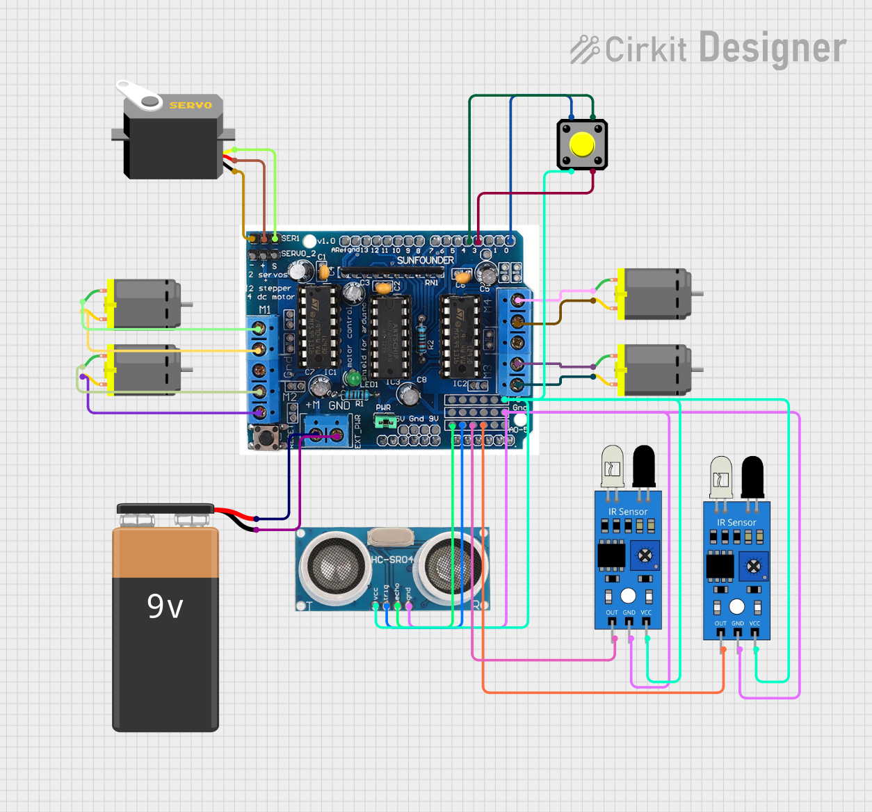
Circuit Documentation
Summary
The circuit in question is designed to control multiple DC motors, a servo motor, an ultrasonic sensor, and IR sensors, all interfaced with an L293D motor driver shield. The circuit is powered by a 9V battery and includes a pushbutton for user input. The L293D driver shield is the central component that interfaces with the microcontroller (not specified in the provided data) to control the motors and read sensor data.
Component List
DC Motor
- Description: A standard DC motor used for creating rotational motion.
- Pins: pin 1, pin 2
Servo
- Description: A servo motor capable of precise control of angular position.
- Pins: gnd, vcc, pulse
Ultrasonic Sensor
- Description: A sensor that measures distance by emitting ultrasonic waves and measuring the time taken for the echo to return.
- Pins: +VCC, Trigger, Echo, GND
L293D Driver Shield
- Description: A motor driver shield that can drive up to 4 DC motors or 2 stepper motors, and has pins for a servo motor and additional sensors.
- Pins: 5v, GND, A0-A5, M+, M1-M4, 0-9, 10-12, gnd, Aref, ser1, Servo2, +, -, 9v
IR Sensor
- Description: An infrared sensor used for detecting obstacles or receiving IR signals.
- Pins: out, gnd, vcc
9V Battery
- Description: A standard 9V battery used as the power source for the circuit.
- Pins: -, +
Pushbutton
- Description: A simple pushbutton switch used for user input.
- Pins: Pin 1, Pin 2, Pin 3, Pin 4
Wiring Details
DC Motor
- Connected to the L293D driver shield's motor output pins (M1-M4).
Servo
- GND: Connected to the L293D driver shield's ground (-).
- VCC: Connected to the L293D driver shield's positive (+).
- Pulse: Connected to the L293D driver shield's servo control pin (ser1).
Ultrasonic Sensor
- +VCC: Connected to the L293D driver shield's 5v.
- Trigger: Connected to the L293D driver shield's A1.
- Echo: Connected to the L293D driver shield's A0.
- GND: Connected to the L293D driver shield's ground (GND).
L293D Driver Shield
- 5v: Powers the IR sensors and the ultrasonic sensor.
- GND: Common ground for the servo, IR sensors, ultrasonic sensor, and 9V battery.
- M+: Connected to the 9V battery's positive (+).
- GND: Connected to the 9V battery's negative (-).
- Motor Outputs (M1-M4): Connected to the respective DC motors.
- A0, A1: Connected to the ultrasonic sensor's Echo and Trigger pins.
- A2, A3: Connected to the IR sensors' output pins.
- 0, 3, 4: Connected to the pushbutton's pins.
IR Sensor
- VCC: Connected to the L293D driver shield's 5v.
- GND: Connected to the L293D driver shield's ground (GND).
- Out: Connected to the L293D driver shield's analog pins (A2, A3).
9V Battery
- +: Connected to the L293D driver shield's motor power input (M+).
- -: Connected to the L293D driver shield's ground (GND).
Pushbutton
- Pin 1: Connected to the L293D driver shield's digital pin 0.
- Pin 2: Connected to the L293D driver shield's 5v.
- Pin 3: Connected to the L293D driver shield's digital pin 3.
- Pin 4: Connected to the L293D driver shield's digital pin 4.
Code Documentation
No code was provided for the microcontrollers in the circuit. If code is available, it should be documented here with explanations for initialization, main loop, function definitions, and any interrupt service routines. The code would typically include setup for the pins, control logic for the motors and servo, reading sensor data, and handling user input from the pushbutton.