
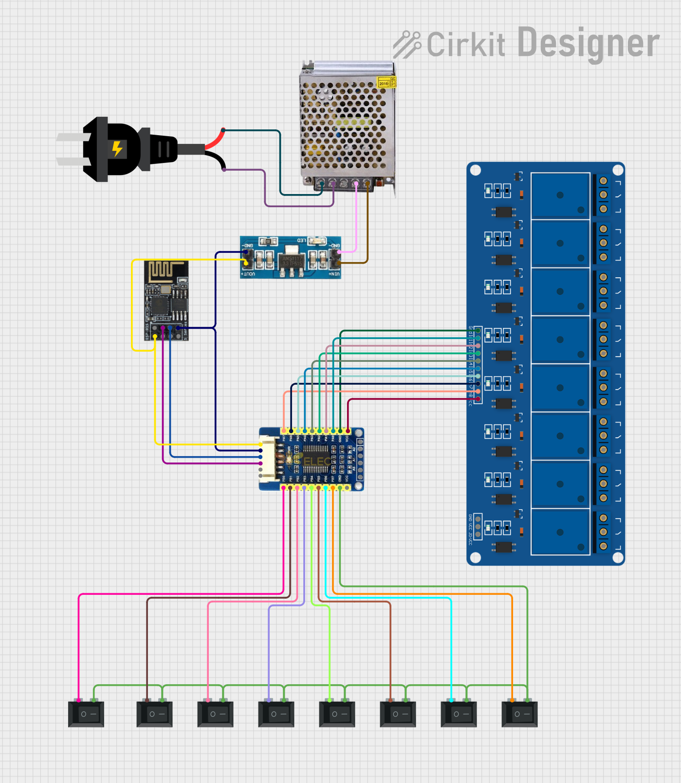
Circuit Documentation
Summary
This circuit is designed to control an 8-channel relay module using a WiFi module (ESP8266-01) and an I/O expansion board (MCP23017). The circuit includes multiple rocker switches for manual control of the relays. The power supply is provided by a 5V 5A power supply, and a 3.3V converter is used to power the ESP8266-01 and MCP23017.
Component List
Wifi module ESP8266-01
- Description: A WiFi module used for wireless communication.
- Pins: RX, GPIO0, GPIO2, GND, +3V3, Reset, CH-PD Chip power down, TX
MCP23017 I/O Expansion Board
- Description: An I/O expansion board used to control multiple I/O pins via I2C.
- Pins: VCC, GND, SDA, SCL, INTA, INTB, PB0, PB1, PB2, PB3, PB4, PB5, PB6, PB7, PA0, PA1, PA2, PA3, PA4, PA5, PA6, PA7
5V 8 Channel Relay Module
- Description: A relay module used to control high-power devices.
- Pins: NC, COM, NO, GND, VCC, JD-VCC, IN8, IN7, IN6, IN5, IN4, IN3, IN2, IN1
Rocker Switch (SPST)
- Description: A single-pole single-throw switch used for manual control.
- Pins: 1, 2
3.3V Converter
- Description: A voltage converter used to step down 5V to 3.3V.
- Pins: GND, Vout, Vin
Power Supply 5V 5A
- Description: A power supply providing 5V at 5A.
- Pins: 220V Positive Pole (AC), 220V Negative Pole (AC), GND, GND (DC), 12V-24V Output (DC)
AC Source
- Description: An AC power source.
- Pins: +, -
Wiring Details
Wifi module ESP8266-01
- GPIO0 is connected to SCL of the MCP23017 I/O Expansion Board.
- GPIO2 is connected to SDA of the MCP23017 I/O Expansion Board.
- GND is connected to GND of the 3.3V Converter and MCP23017 I/O Expansion Board.
- +3V3 is connected to Vout of the 3.3V Converter.
MCP23017 I/O Expansion Board
- SCL is connected to GPIO0 of the Wifi module ESP8266-01.
- SDA is connected to GPIO2 of the Wifi module ESP8266-01.
- GND is connected to GND of the 3.3V Converter and Wifi module ESP8266-01.
- VCC is connected to Vout of the 3.3V Converter.
- PB0 is connected to 1 of a Rocker Switch (SPST).
- PB1 is connected to 1 of a Rocker Switch (SPST).
- PB2 is connected to 1 of a Rocker Switch (SPST).
- PB3 is connected to 1 of a Rocker Switch (SPST).
- PB4 is connected to 1 of a Rocker Switch (SPST).
- PB5 is connected to 1 of a Rocker Switch (SPST).
- PB6 is connected to 1 of a Rocker Switch (SPST).
- PB7 is connected to 1 of a Rocker Switch (SPST).
- PA0 is connected to IN1 of the 5V 8 Channel Relay Module.
- PA1 is connected to IN2 of the 5V 8 Channel Relay Module.
- PA2 is connected to IN3 of the 5V 8 Channel Relay Module.
- PA3 is connected to IN4 of the 5V 8 Channel Relay Module.
- PA4 is connected to IN5 of the 5V 8 Channel Relay Module.
- PA5 is connected to IN6 of the 5V 8 Channel Relay Module.
- PA6 is connected to IN7 of the 5V 8 Channel Relay Module.
- PA7 is connected to IN8 of the 5V 8 Channel Relay Module.
5V 8 Channel Relay Module
- VCC is connected to VCC of the MCP23017 I/O Expansion Board.
- GND is connected to GND of the MCP23017 I/O Expansion Board.
- IN1 is connected to PA0 of the MCP23017 I/O Expansion Board.
- IN2 is connected to PA1 of the MCP23017 I/O Expansion Board.
- IN3 is connected to PA2 of the MCP23017 I/O Expansion Board.
- IN4 is connected to PA3 of the MCP23017 I/O Expansion Board.
- IN5 is connected to PA4 of the MCP23017 I/O Expansion Board.
- IN6 is connected to PA5 of the MCP23017 I/O Expansion Board.
- IN7 is connected to PA6 of the MCP23017 I/O Expansion Board.
- IN8 is connected to PA7 of the MCP23017 I/O Expansion Board.
Rocker Switch (SPST)
- 1 of each switch is connected to PB0, PB1, PB2, PB3, PB4, PB5, PB6, and PB7 of the MCP23017 I/O Expansion Board respectively.
- 2 of all switches are interconnected and connected to GND of the MCP23017 I/O Expansion Board.
3.3V Converter
- GND is connected to GND of the Wifi module ESP8266-01, MCP23017 I/O Expansion Board, and Power Supply 5V 5A.
- Vout is connected to +3V3 of the Wifi module ESP8266-01 and VCC of the MCP23017 I/O Expansion Board.
- Vin is connected to 12V-24V Output (DC) of the Power Supply 5V 5A.
Power Supply 5V 5A
- 220V Positive Pole (AC) is connected to + of the AC Source.
- 220V Negative Pole (AC) is connected to - of the AC Source.
- GND (DC) is connected to GND of the 3.3V Converter.
- 12V-24V Output (DC) is connected to Vin of the 3.3V Converter.
AC Source
- + is connected to 220V Positive Pole (AC) of the Power Supply 5V 5A.
- - is connected to 220V Negative Pole (AC) of the Power Supply 5V 5A.
Code Documentation
#include <Wire.h>
#include <Adafruit_MCP23X17.h>

Adafruit_MCP23X17 mcp;

const int relayPins[] = {0, 1, 2, 3, 4, 5, 6, 7}; // MCP23017 pins for relays
const int switchPins[] = {8, 9, 10, 11, 12, 13, 14, 15}; // MCP23017 pins for switches

bool relayStates[8] = {false, false, false, false, false, false, false, false}; // Store relay states

void setup() {
  Serial.begin(115200);
  mcp.begin_I2C(); // Initialize MCP23017 with I2C

  // Initialize relay and switch pins
  for (int i = 0; i < 8; i++) {
    mcp.pinMode(relayPins[i], OUTPUT);
    mcp.digitalWrite(relayPins[i], LOW); // Relay off
    mcp.pinMode(switchPins[i], INPUT);
    mcp.digitalWrite(switchPins[i], HIGH); // Enable internal pull-up resistor
  }
}

void loop() {
  // Check switches for manual control
  for (int i = 0; i < 8; i++) {
    if (mcp.digitalRead(switchPins[i]) == LOW) {
      delay(50); // Debounce delay
      if (mcp.digitalRead(switchPins[i]) == LOW) {
        relayStates[i] = !relayStates[i];
        mcp.digitalWrite(relayPins[i], relayStates