ESP32-Based Smart AC Control System with Temperature and Humidity Monitoring
Circuit Documentation
Summary
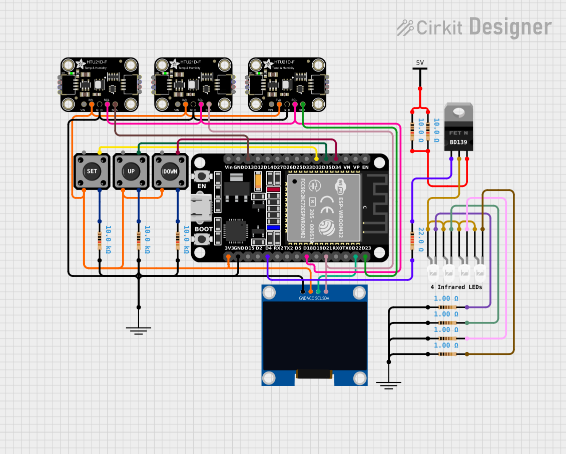
This circuit is designed to control a room air conditioner (AC) using an ESP32 microcontroller. It includes tactile switches for user input, resistors for current limiting and pull-up configurations, MOSFETs for switching, temperature and humidity sensors for environmental monitoring, and an OLED display for user interface. The circuit is capable of reading temperature and humidity data, displaying information, and sending IR signals to control the AC unit based on the environmental readings and user inputs.
Component List
Tactile Switch Buttons - 12mm Square
- Description: Momentary push buttons used for user input.
- Pins: 4 (labeled as 1, 2, 3, 4)
Resistor
- Description: Passive two-terminal electrical component used to limit current or divide voltages.
- Pins: 2 (labeled as pin1, pin2)
- Values: 10 Ohms, 22 Ohms, 1 Ohm, 10 kOhms
GND (Ground)
- Description: Common reference point for the electrical return path.
nMOS Transistor (MOSFET)
- Description: Type of field-effect transistor used for switching or amplifying signals.
- Pins: 3 (labeled as gate, drain, source)
ESP32 (30 pin)
- Description: Microcontroller with Wi-Fi and Bluetooth capabilities.
- Pins: 30 (labeled as EN, VP, VN, D34, D35, D32, D33, D25, D26, D27, D14, D12, D13, GND, Vin, D23, D22, TX0, RX0, D21, D19, D18, D5, TX2, RX2, D4, D2, D15, 3V3)
Adafruit HTU21D-F Temperature & Humidity Sensor
- Description: Digital temperature and humidity sensor.
- Pins: 5 (labeled as VCC, 3.3V, GND, SCL, SDA)
Vcc (Voltage Common Collector)
- Description: Positive supply voltage connection.
LED: Two Pin (white)
- Description: Light Emitting Diode used as an indicator.
- Pins: 2 (labeled as cathode, anode)
128x64 OLED Display (I2C IIC SPI Serial)
- Description: Small display for visual output.
- Pins: 4 (labeled as GND, SDA, SCL, VCC)
Comment
- Description: Textual annotations or comments within the circuit design.
Wiring Details
Tactile Switch Buttons - 12mm Square
- Pin 2 connected to ESP32 pin D34, D35, D32 (for different instances of the switch)
- Pin 3 connected to 3.3V power rail
- Pin 4 connected to respective 10 kOhm pull-up resistors
Resistor
- 10 Ohm resistors connected to Vcc
- 22 Ohm resistor connected to ESP32 pin D4 and MOSFET gate
- 1 Ohm resistors connected to LED cathodes and GND
- 10 kOhm resistors connected to tactile switch pin 4 and GND
nMOS Transistor (MOSFET)
- Gate connected to 22 Ohm resistor and ESP32 pin D4
- Drain connected to anodes of LEDs
- Source connected to 10 Ohm resistors and GND
ESP32 (30 pin)
- Digital pins D34, D35, D32 connected to tactile switches
- Digital pins D13, D23, D21, D18 connected to SDA lines of temperature sensors and OLED display
- Digital pin D22 connected to SCL line of OLED display
- Digital pin D4 connected to gate of MOSFET through a 22 Ohm resistor
- 3V3 pin connected to 3.3V power rail of tactile switches and temperature sensors
- GND pin connected to ground rail
Adafruit HTU21D-F Temperature & Humidity Sensor
- SDA connected to ESP32 digital pins D13, D23, D21 (shared with other sensors and display)
- SCL connected to ESP32 digital pin D18 (shared with other sensors)
- GND connected to ground rail
- 3.3V connected to 3.3V power rail
LED: Two Pin (white)
- Anode connected to drain of MOSFET
- Cathode connected to 1 Ohm resistors and GND
128x64 OLED Display (I2C IIC SPI Serial)
- SDA connected to ESP32 digital pin D21 (shared with temperature sensors)
- SCL connected to ESP32 digital pin D22
- VCC connected to 3.3V power rail
- GND connected to ground rail
Documented Code
The code for the ESP32 microcontroller is written in C++ and is used to control the AC unit based on temperature and humidity readings. It includes the following functionalities:
- Reading temperature and humidity from the HTU21D-F sensors
- Displaying the current temperature, humidity, and system status on the OLED display
- Responding to button presses to navigate through a menu system
- Storing temperature set points in EEPROM
- Sending IR commands to the AC unit to turn it on/off or change the temperature
The code is organized into several files:
controller_main.ino: Main program file that includes the setup and loop functions.displaycont.h: Contains functions for controlling the OLED display.eepromcont.h: Manages EEPROM read/write operations for storing temperature set points.htuCont.h: Functions for reading temperature and humidity from the HTU21D-F sensors.myIRsender.h: Sends IR commands using predefined raw codes.ircodes.h: Contains raw IR codes for controlling the AC unit.wserialmonitor.h: (Optional) For debugging purposes, allows serial communication over Wi-Fi.
The main program initializes the system, reads sensor data, updates the display, and sends IR commands based on user input and temperature thresholds. It also handles EEPROM storage for persistent settings across reboots.
The code makes use of several libraries, including Adafruit_SSD1306 for the display, Adafruit_HTU21DF for the sensors, and IRremoteESP8266 for sending IR signals.
For detailed code documentation, please refer to the comments within each file and the functions they contain. The code is structured to be modular, with each file handling a specific aspect of the system's functionality.