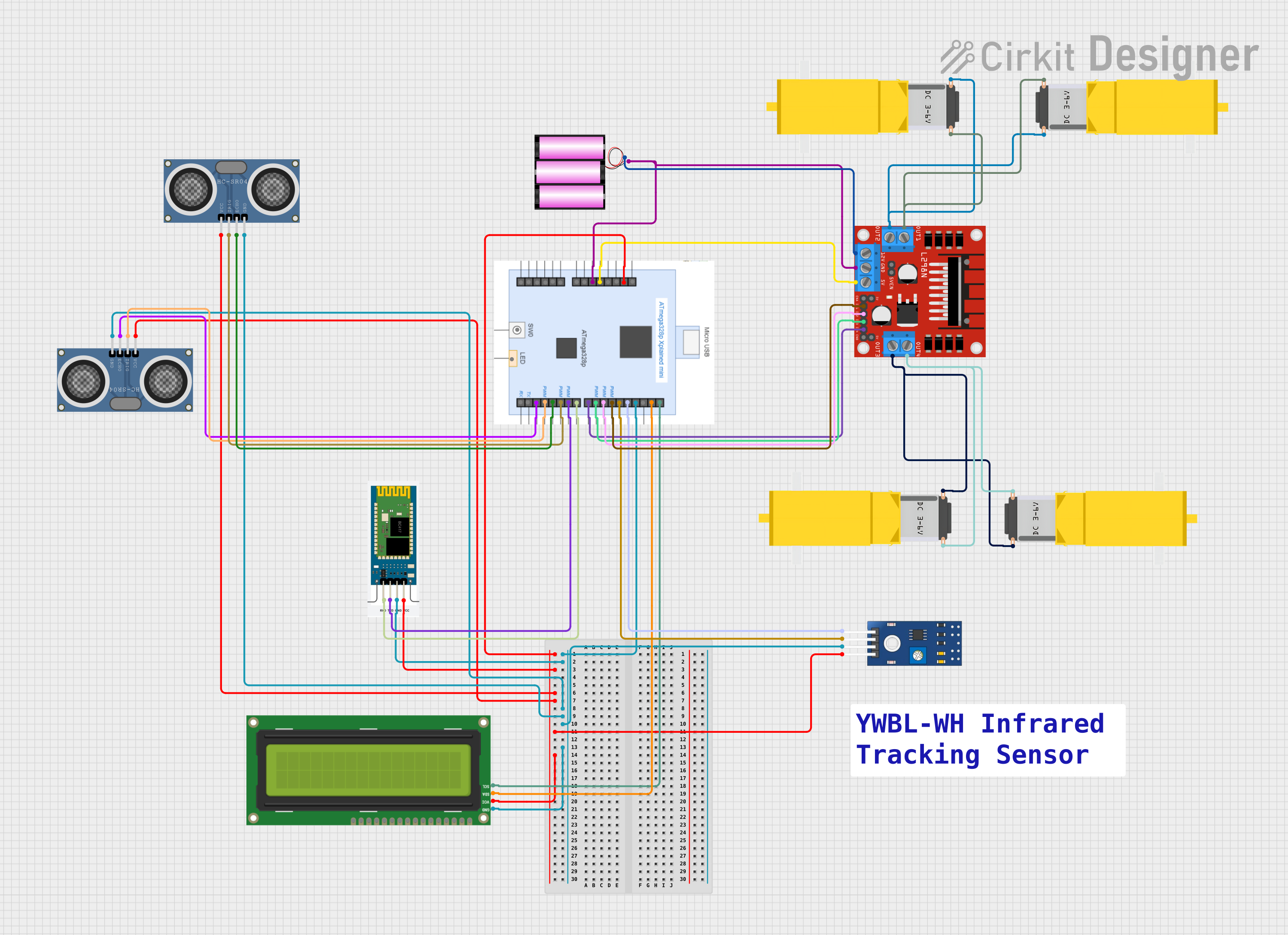
ATmega328P-Based Obstacle Avoidance Robot with Bluetooth Interface and Ultrasonic Sensors

Circuit Documentation
Summary
The circuit is designed to control multiple DC gearmotors using an L298N motor driver, interfaced with an ATmega328P Xplained Mini microcontroller. The circuit includes ultrasonic distance sensors (HC-SR04) for distance measurement, an IR sensor (TCRT 5000) for object detection, and an I2C LCD screen for displaying information. A Bluetooth module (HC-06) is incorporated for wireless communication. The entire circuit is powered by a 12V battery, with voltage regulation provided by the microcontroller and motor driver for their respective operating voltages.
Component List
Power Supply
- Battery 12V: Provides the main power source for the motor driver and is stepped down for other components.
Actuators
- Gearmotor DC / Motorreductor: Four DC gearmotors are used for actuation purposes.
Microcontroller
- ATmega328P Xplained Mini: Serves as the central processing unit, controlling the motors, sensors, and communication modules.
Sensors
- HC-SR04 Ultrasonic Distance Sensor: Two sensors are used for measuring distances by emitting ultrasonic waves.
- TCRT 5000 IR Sensor: An infrared sensor used for object detection.
Communication Module
- HC-06: A Bluetooth module for wireless communication with other devices.
Display
- I2C LCD 16x2 Screen: Displays information such as sensor readings and system status.
Motor Driver
- L298N DC Motor Driver: Controls the direction and speed of the DC gearmotors.
Wiring Details
Battery 12V
- +: Connected to the 12V input of the L298N motor driver.
- -: Connected to the GND of the ATmega328P and the L298N motor driver.
Gearmotor DC / Motorreductor
- Pin1 and Pin2: Connected to the output pins of the L298N motor driver to control the direction of the motors.
ATmega328P Xplained Mini
- VCC: Connected to the VCC pins of the HC-06, HC-SR04 sensors, TCRT 5000 sensor, and I2C LCD screen.
- GND: Common ground for the circuit.
- Digital Pins (D2-D13): Control pins for the HC-SR04 sensors, HC-06 Bluetooth module, L298N motor driver, and TCRT 5000 sensor.
- Analog Pins (A4, A5): I2C communication pins connected to the SDA and SCL pins of the I2C LCD screen.
HC-SR04 Ultrasonic Distance Sensor
- VCC: Power supply (5V from ATmega328P).
- GND: Ground connection.
- TRIG: Trigger pin connected to a digital pin on the ATmega328P for initiating distance measurement.
- ECHO: Echo pin connected to a digital pin on the ATmega328P to receive the reflected signal.
TCRT 5000 IR Sensor
- VCC: Power supply (5V from ATmega328P).
- GND: Ground connection.
- DO: Digital output connected to a digital pin on the ATmega328P.
- AO: Analog output connected to a digital pin on the ATmega328P.
HC-06 Bluetooth Module
- VCC: Power supply (5V from ATmega328P).
- GND: Ground connection.
- TXD: Transmit pin connected to a digital pin on the ATmega328P.
- RXD: Receive pin connected to a digital pin on the ATmega328P.
I2C LCD 16x2 Screen
- VCC (5V): Power supply (5V from ATmega328P).
- GND: Ground connection.
- SDA: I2C data line connected to the A4 pin on the ATmega328P.
- SCL: I2C clock line connected to the A5 pin on the ATmega328P.
L298N DC Motor Driver
- 12V: Power supply from the 12V battery.
- GND: Ground connection.
- 5V: 5V output used to power the ATmega328P.
- IN1-IN4: Input control pins connected to digital pins on the ATmega328P.
- OUT1-OUT4: Output pins connected to the pins of the DC gearmotors.
Documented Code
Since no code was provided, this section is left blank. When code is available, it should be documented here with explanations of functions, algorithms, and any relevant comments to understand the program flow and operation.