Arduino-Controlled Line-Following Robot with Dual IR Sensors and L298N Motor Driver
Circuit Documentation
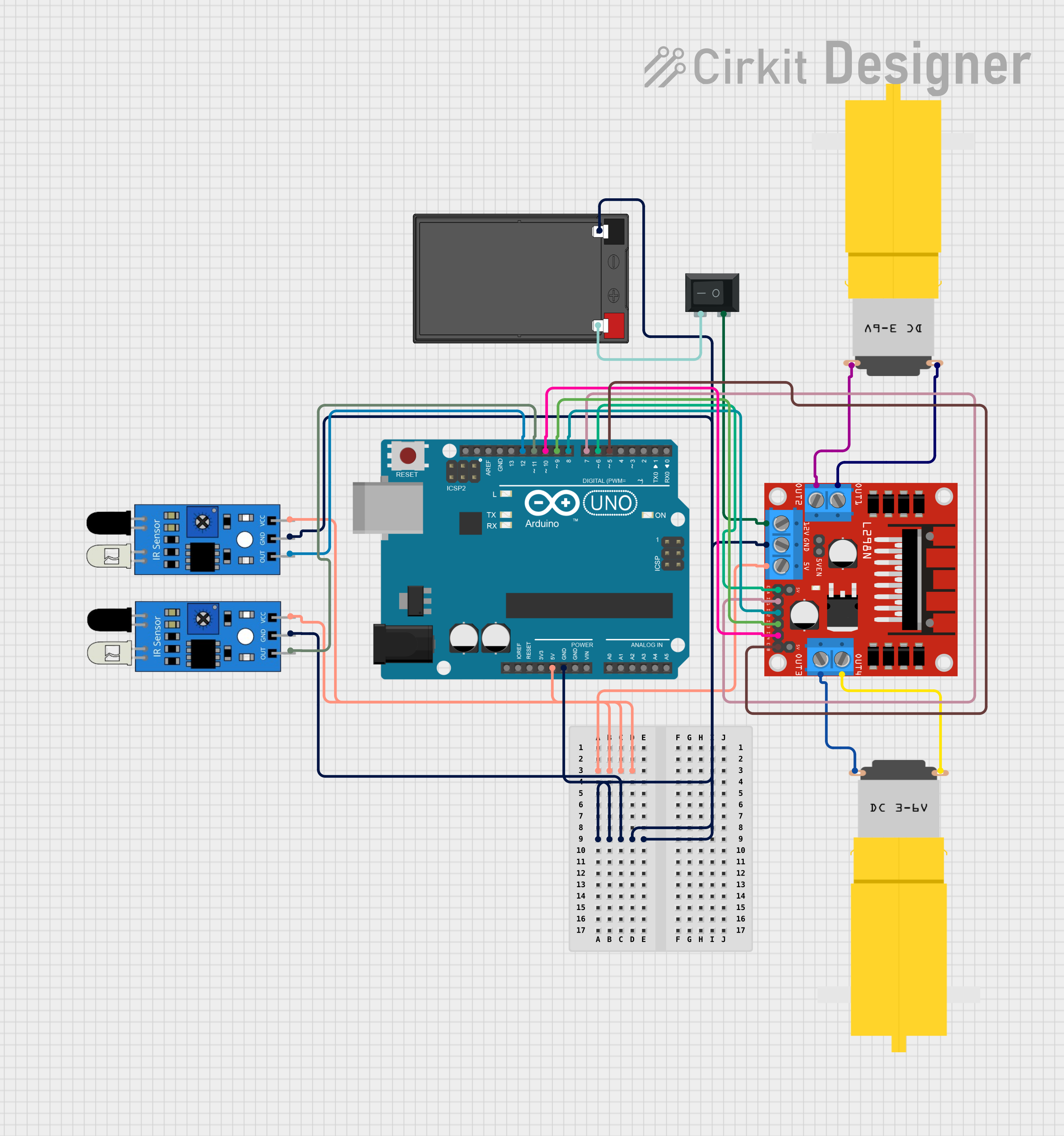
Summary
This circuit is designed to control a pair of DC motors using an Arduino UNO microcontroller and an L298N DC motor driver. It includes two IR sensors for input, which are likely used for line tracking or obstacle detection. The motors are powered by a 12V 7Ah battery, and a rocker switch is used to control the power supply to the motor driver. The Arduino UNO is programmed to read the IR sensor inputs and accordingly control the speed and direction of the motors through the L298N driver.
Component List
Arduino UNO
- Microcontroller board based on the ATmega328P
- Provides digital and analog I/O pins
- Used for controlling the logic of the circuit
L298N DC Motor Driver
- Dual H-bridge motor driver
- Capable of driving two DC motors or one stepper motor
- Used to control the direction and speed of the motors
IR Sensors
- Infrared sensors for detecting proximity or line tracking
- Each sensor has an output, ground, and VCC pin
- Used to provide input signals to the Arduino based on the presence of an object or a line
DC Motors (Motor amarillo motorreductor hobby)
- Yellow geared DC motors
- Operate on voltage provided by the motor driver
- Used to drive the wheels or other mechanical parts of the system
12V 7Ah Battery
- Lead-acid rechargeable battery
- Provides the power source for the motor driver and indirectly for the motors
Rocker Switch (SPST)
- Single Pole Single Throw (SPST) switch
- Used to control the connection between the battery and the motor driver
Wiring Details
Arduino UNO
5VandGNDpins are connected to the 5V and ground buses, respectively, providing power to the IR sensors.- Digital pins
D5toD12are used to interface with the L298N motor driver and the IR sensors.
L298N DC Motor Driver
5Vpin is connected to the 5V bus.GNDpin is connected to the ground bus.12Vpin is connected to the rocker switch to receive power from the battery.ENAandENBpins are connected to Arduino pinsD6andD5for enabling the motor outputs.IN1toIN4pins are connected to Arduino pinsD7toD10for controlling the motor directions.OUT1toOUT4pins are connected to the DC motors.
IR Sensors
VCCpins are connected to the 5V bus.GNDpins are connected to the ground bus.OUTpins are connected to Arduino pinsD11andD12.
DC Motors
- One terminal of each motor is connected to the
OUT1/OUT3of the motor driver. - The other terminal of each motor is connected to the
OUT2/OUT4of the motor driver.
12V 7Ah Battery
12v +pin is connected to one terminal of the rocker switch.12v -pin is connected to the ground bus.
Rocker Switch (SPST)
- One terminal is connected to the
12Vpin of the motor driver. - The other terminal is connected to the
12v +pin of the battery.
Documented Code
#define IR_SENSOR_RIGHT 11
#define IR_SENSOR_LEFT 12
#define MOTOR_SPEED 180

// Right motor
int enableRightMotor = 6;
int rightMotorPin1 = 7;
int rightMotorPin2 = 8;

// Left motor
int enableLeftMotor = 5;
int leftMotorPin1 = 9;
int leftMotorPin2 = 10;

void setup() {
  // Configure timer for PWM frequency adjustment
  TCCR0B = TCCR0B & B11111000 | B00000010;

  // Set motor driver pins as outputs
  pinMode(enableRightMotor, OUTPUT);
  pinMode(rightMotorPin1, OUTPUT);
  pinMode(rightMotorPin2, OUTPUT);
  pinMode(enableLeftMotor, OUTPUT);
  pinMode(leftMotorPin1, OUTPUT);
  pinMode(leftMotorPin2, OUTPUT);

  // Set IR sensor pins as inputs
  pinMode(IR_SENSOR_RIGHT, INPUT);
  pinMode(IR_SENSOR_LEFT, INPUT);

  // Initialize motors to stop
  rotateMotor(0, 0);
}

void loop() {
  // Read IR sensor values
  int rightIRSensorValue = digitalRead(IR_SENSOR_RIGHT);
  int leftIRSensorValue = digitalRead(IR_SENSOR_LEFT);

  // Control logic based on sensor input
  if (rightIRSensorValue == LOW && leftIRSensorValue == LOW) {
    // Move forward
    rotateMotor(MOTOR_SPEED, MOTOR_SPEED);
  } else if (rightIRSensorValue == HIGH && leftIRSensorValue == LOW) {
    // Turn right
    rotateMotor(-MOTOR_SPEED, MOTOR_SPEED);
  } else if (rightIRSensorValue == LOW && leftIRSensorValue == HIGH) {
    // Turn left
    rotateMotor(MOTOR_SPEED, -MOTOR_SPEED);
  } else {
    // Stop
    rotateMotor(0, 0);
  }
}

void rotateMotor(int rightMotorSpeed, int leftMotorSpeed) {
  // Set motor direction and speed
  if (rightMotorSpeed < 0) {
    digitalWrite(rightMotorPin1, LOW);
    digitalWrite(rightMotorPin2, HIGH);
  } else if (rightMotorSpeed > 0) {
    digitalWrite(rightMotorPin1, HIGH);
    digitalWrite(rightMotorPin2, LOW);
  } else {
    digitalWrite(rightMotorPin1, LOW);
    digitalWrite(rightMotorPin2, LOW);
  }

  if (leftMotorSpeed < 0) {
    digitalWrite(leftMotorPin1, LOW);
    digitalWrite(leftMotorPin2, HIGH);
  } else if (leftMotorSpeed > 0) {
    digitalWrite(leftMotorPin1, HIGH);
    digitalWrite(leftMotorPin2, LOW);
  } else {
    digitalWrite(leftMotorPin1, LOW);
    digitalWrite(leftMotorPin2, LOW);
  }

  // Apply PWM to enable pins
  analogWrite(enableRightMotor, abs(rightMotorSpeed));
  analogWrite(enableLeftMotor, abs(leftMotorSpeed));
}
This code is designed to be uploaded to the Arduino UNO microcontroller. It initializes the motor driver and IR sensor pins, then enters a loop where it reads the IR sensor values and controls the motors accordingly. The rotateMotor function is used to set the direction and speed of the motors based on the sensor inputs.