Arduino UNO Based IR Sensor Alarm with Servo Motor and I2C LCD Display
Circuit Documentation
Summary of the Circuit
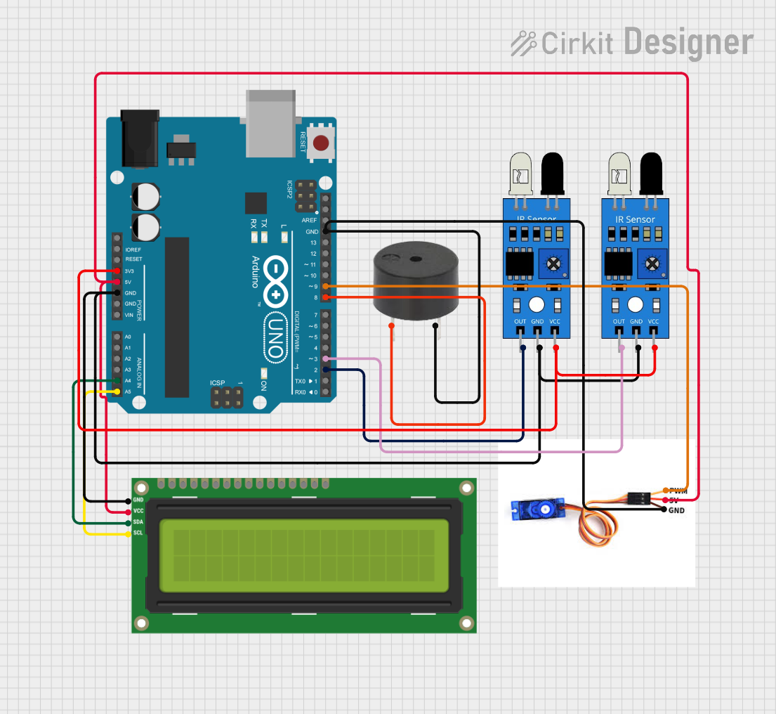
This circuit is designed around an Arduino UNO microcontroller and includes various peripherals such as IR sensors, an SG90 servo motor, an I2C LCD 16x2 screen, and a buzzer. The IR sensors are powered by the 3.3V output from the Arduino UNO, while the servo motor, LCD screen, and buzzer are powered by the 5V output. The ground connections are shared among all components and the Arduino UNO. The LCD screen communicates with the Arduino UNO via the I2C protocol, using the SDA and SCL lines. The servo motor is controlled by a PWM signal from the Arduino UNO, and the buzzer is activated by a digital output. The IR sensors are connected to digital inputs to detect the presence of objects.
Component List
Arduino UNO
- Microcontroller board based on the ATmega328P
- Provides digital I/O pins, analog inputs, and various power outputs
IR Sensor
- Infrared sensor for object detection
- Includes an output pin to signal the detection of an object
SG90 Servo Motor
- Small and lightweight servo motor
- Controlled by PWM signal
I2C LCD 16x2 Screen
- Liquid crystal display with 16 characters by 2 lines
- Uses I2C communication protocol
Buzzer
- Electronic buzzer for audible alerts
- Activated by a digital signal
Wiring Details
Arduino UNO
- 3.3V pin connected to the VCC pins of both IR sensors
- 5V pin connected to the 5V pin of the SG90 servo motor and VCC (5V) pin of the I2C LCD 16x2 screen
- GND pin connected to the GND pins of both IR sensors, the SG90 servo motor, the I2C LCD 16x2 screen, and the buzzer
- A4 (SDA) pin connected to the SDA pin of the I2C LCD 16x2 screen
- A5 (SCL) pin connected to the SCL pin of the I2C LCD 16x2 screen
- D9 pin connected to the PWM pin of the SG90 servo motor
- D8 pin connected to the PIN pin of the buzzer
- D3 pin connected to the OUT pin of one IR sensor
- D2 pin connected to the OUT pin of the other IR sensor
IR Sensors
- VCC pin connected to the 3.3V pin of the Arduino UNO
- GND pin connected to the GND pin of the Arduino UNO
- OUT pin of one sensor connected to the D3 pin of the Arduino UNO
- OUT pin of the other sensor connected to the D2 pin of the Arduino UNO
SG90 Servo Motor
- 5V pin connected to the 5V pin of the Arduino UNO
- GND pin connected to the GND pin of the Arduino UNO
- PWM pin connected to the D9 pin of the Arduino UNO
I2C LCD 16x2 Screen
- SCL pin connected to the A5 (SCL) pin of the Arduino UNO
- SDA pin connected to the A4 (SDA) pin of the Arduino UNO
- VCC (5V) pin connected to the 5V pin of the Arduino UNO
- GND pin connected to the GND pin of the Arduino UNO
Buzzer
- PIN pin connected to the D8 pin of the Arduino UNO
- GND pin connected to the GND pin of the Arduino UNO
Documented Code
void setup() {
  // put your setup code here, to run once:

}

void loop() {
  // put your main code here, to run repeatedly:

}
The provided code is a template for the Arduino UNO microcontroller. The setup() function is called once when the microcontroller is powered on or reset. It is used to initialize the pins and set the initial state of the circuit. The loop() function is called repeatedly and contains the main logic of the program. This is where you would add code to read the IR sensors, control the servo motor, display information on the LCD screen, and activate the buzzer based on certain conditions.