
ESP32-Based Portable Multi-Functional Tracker with GSM, GPS, and Audio Recording
View and Edit Project In Cirkit Designer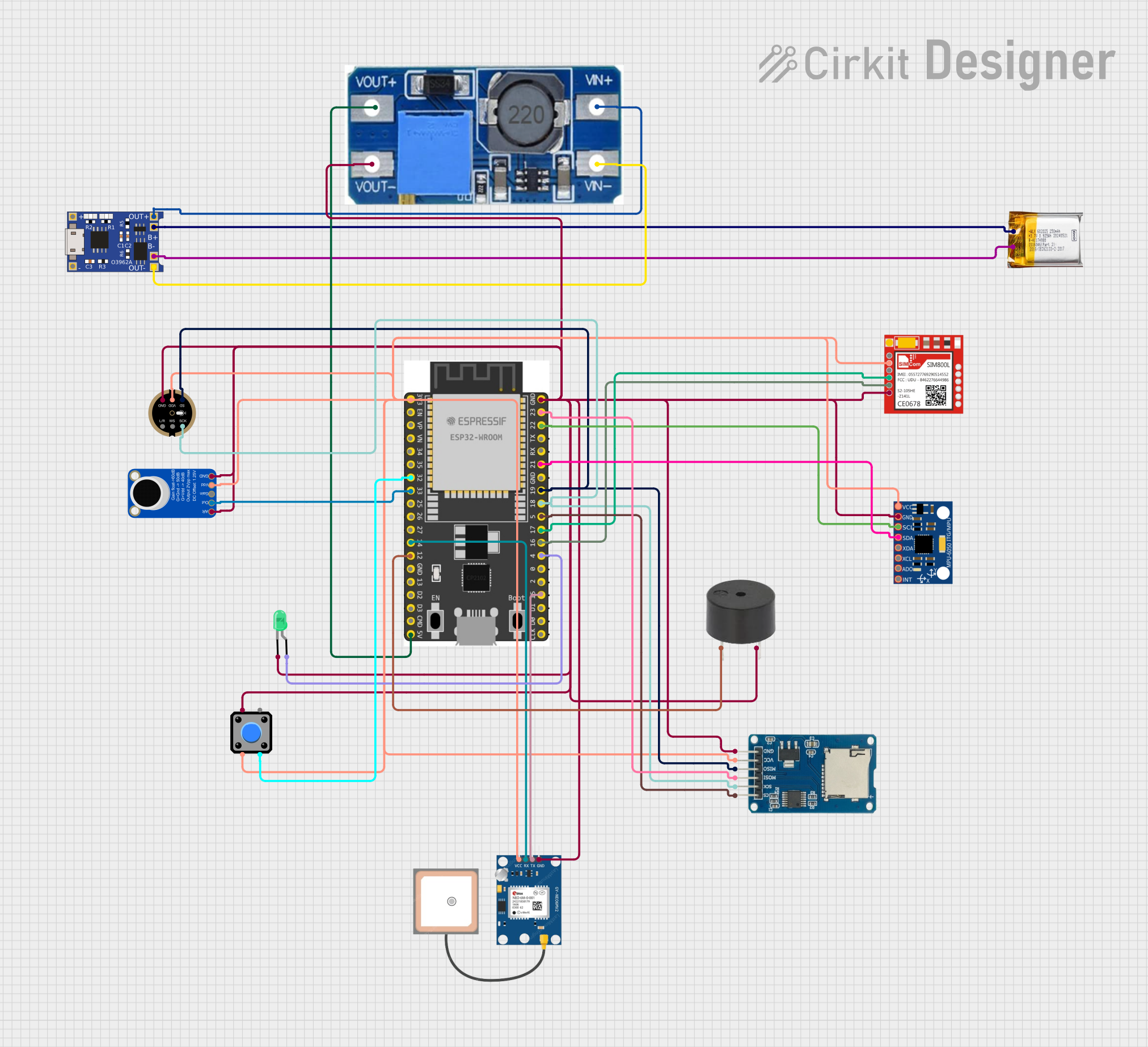
Circuit Documentation
Summary
This circuit integrates various components to create a multifunctional system. It includes an ESP32 Wroom Dev Kit as the main microcontroller, interfaced with a SIM800L GSM module, a GPS NEO 6M module for location tracking, an INMP441 microphone and an Adafruit MAX9814 microphone amplifier for audio input, an MPU-6050 for motion tracking, a Micro SD Card Module for data storage, and a Step Up Boost Power Converter for voltage regulation. Additionally, the circuit features a buzzer for audio output, a pushbutton for user input, and an LED for visual indication. The power management is handled by a TP4056 charging module and a 3.7V LiPo battery.
Component List
ESP 32 Wroom Dev Kit
- Microcontroller with WiFi and Bluetooth capabilities.
- Pins: 3V3, EN, VP, VN, GPIOs, GND, SD2, SD3, CMD, V5, TXD, RXD.
Sim800l
- GSM/GPRS module for cellular communication.
- Pins: NET, RST, VCC, RXD, TXD, GND.
GPS NEO 6M
- GPS module for location tracking.
- Pins: VCC, RX, TX, GND.
INMP441 FRONT MIC
- I2S digital output microphone.
- Pins: L/R, WS, SCK, SD, VDD, GND.
Adafruit MAX9814 Electret Microphone Amplifier
- Microphone amplifier with automatic gain control.
- Pins: GND, VDD, GAIN, OUTPUT, A/R.
Micro SD Card Module
- Module for reading and writing to micro SD cards.
- Pins: cs, sck, mosi, miso, vcc, gnd.
Step Up Boost Power Converter, Adjustable Voltage Regulator
- Module to step up voltage to a desired level.
- Pins: VOUT+, VOUT-, VIN+, VIN-.
Buzzer
- Audio output device.
- Pins: PIN, GND.
MPU-6050
- Motion tracking device with a gyroscope and accelerometer.
- Pins: VCC, GND, SCL, SDA, XDA, XCL, AD0, INT.
3.7v LiPo Battery
- Rechargeable battery for power supply.
- Pins: +Ve, GND.
Pushbutton
- User input device.
- Pins: Pin 2, Pin 1, Pin 3, Pin 4.
TP4056
- Lithium battery charging module.
- Pins: OUT-, B-, B+, OUT+, IN-, IN+.
LED: Two Pin (green)
- Visual indicator.
- Pins: cathode, anode.
Wiring Details
ESP 32 Wroom Dev Kit
- 3V3: Connected to VCC of various components for power supply.
- GPIO 32: Connected to Pushbutton (Pin 3).
- GPIO 33: Connected to OUTPUT of Adafruit MAX9814 Electret Microphone Amplifier.
- GPIO 14: Connected to RX of GPS NEO 6M and PIN of Buzzer.
- V5: Connected to VOUT+ of Step Up Boost Power Converter.
- GND: Common ground with various components.
- GPIO 23: Connected to mosi of Micro SD Card Module.
- GPIO 22: Connected to SCL of MPU-6050.
- GPIO 21: Connected to SDA of MPU-6050.
- GPIO 19: Connected to miso of Micro SD Card Module and SD of INMP441 FRONT MIC.
- GPIO 18: Connected to sck of Micro SD Card Module and SCK of INMP441 FRONT MIC.
- GPIO 5: Connected to cs of Micro SD Card Module.
- GPIO 17: Connected to RXD of Sim800l.
- GPIO 16: Connected to TXD of Sim800l.
- GPIO 4: Connected to anode of LED: Two Pin (green).
- GPIO 15: Connected to TX of GPS NEO 6M.
Sim800l
- VCC: Connected to 3V3 power net.
- RXD: Connected to GPIO 17 of ESP 32 Wroom Dev Kit.
- TXD: Connected to GPIO 16 of ESP 32 Wroom Dev Kit.
- GND: Connected to common ground.
GPS NEO 6M
- VCC: Connected to 3V3 power net.
- RX: Connected to GPIO 14 of ESP 32 Wroom Dev Kit.
- TX: Connected to GPIO 15 of ESP 32 Wroom Dev Kit.
- GND: Connected to common ground.
INMP441 FRONT MIC
- VDD: Connected to 3V3 power net.
- SCK: Connected to GPIO 18 of ESP 32 Wroom Dev Kit.
- SD: Connected to GPIO 19 of ESP 32 Wroom Dev Kit.
- GND: Connected to common ground.
Adafruit MAX9814 Electret Microphone Amplifier
- VDD: Connected to 3V3 power net.
- OUTPUT: Connected to GPIO 33 of ESP 32 Wroom Dev Kit.
- GND: Connected to common ground.
- A/R: Connected to common ground.
Micro SD Card Module
- vcc: Connected to 3V3 power net.
- cs: Connected to GPIO 5 of ESP 32 Wroom Dev Kit.
- sck: Connected to GPIO 18 of ESP 32 Wroom Dev Kit.
- mosi: Connected to GPIO 23 of ESP 32 Wroom Dev Kit.
- miso: Connected to GPIO 19 of ESP 32 Wroom Dev Kit.
- gnd: Connected to common ground.
Step Up Boost Power Converter, Adjustable Voltage Regulator
- VOUT+: Connected to V5 of ESP 32 Wroom Dev Kit.
- VOUT-: Connected to common ground.
- VIN+: Connected to OUT+ of TP4056.
- VIN-: Connected to OUT- of TP4056.
Buzzer
- PIN: Connected to GPIO 14 of ESP 32 Wroom Dev Kit.
- GND: Connected to common ground.
MPU-6050
- VCC: Connected to 3V3 power net.
- GND: Connected to common ground.
- SCL: Connected to GPIO 22 of ESP 32 Wroom Dev Kit.
- SDA: Connected to GPIO 21 of ESP 32 Wroom Dev Kit.
3.7v LiPo Battery
- +Ve: Connected to B+ of TP4056.
- GND: Connected to B- of TP4056.
Pushbutton
- Pin 2: Connected to 3V3 power net.
- Pin 1: Connected to common ground.
- Pin 3: Connected to GPIO 32 of ESP 32 Wroom Dev Kit.
TP4056
- OUT+: Connected to VIN+ of Step Up Boost Power Converter.
- OUT-: Connected to VIN- of Step Up Boost Power Converter.
- B+: Connected to +Ve of 3.7v LiPo Battery.
- B-: Connected to GND of 3.7v LiPo Battery.
LED: Two Pin (green)
- anode: Connected to GPIO 4 of ESP 32 Wroom Dev Kit.
- cathode: Connected to common ground.
Documented Code
No code has been provided for the microcontrollers in the circuit. The documentation of the code would typically include descriptions of the functions, initialization procedures, main loop, and any interrupt service routines. It would also cover the configuration of peripherals such as GPIOs, communication interfaces (I2C, SPI, UART), and any libraries used for interfacing with the components. Since no code is available, this section remains empty.