
ESP32-Controlled Environmental Monitoring and Watering System
View and Edit Project In Cirkit Designer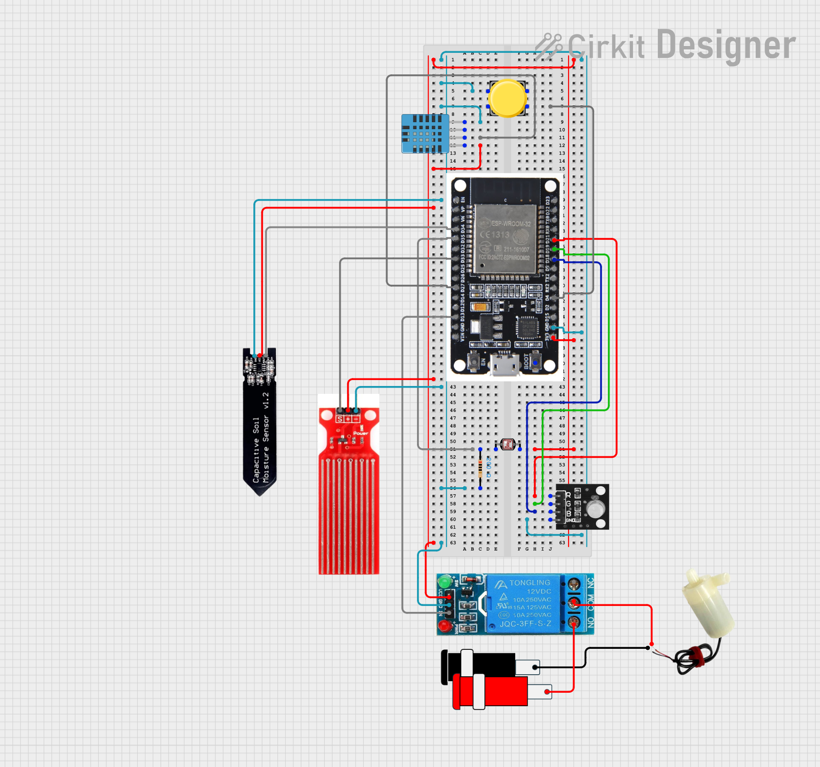
Circuit Documentation
Summary
This circuit is designed to interface various sensors and actuators with an ESP32 microcontroller. The sensors include a DHT11 humidity and temperature sensor, a photocell (LDR), a water sensor, and a soil moisture sensor. Actuators include a 12V single-channel relay and a 5V mini water pump. An RGB LED module and a pushbutton are also part of the circuit for user interaction and feedback. The circuit is powered by a 5V connector, and a resistor is used for the photocell voltage divider. The ESP32 serves as the central processing unit, reading sensor data, controlling the relay and water pump, and managing the LED states.
Component List
DHT11 Humidity and Temperature Sensor
- Pins: VDD, DATA, NULL, GND
- Description: Measures ambient humidity and temperature.
12V Single Channel Relay
- Pins: NC, COM, NO, IN, GND, VCC
- Description: Electromechanical switch used to control the water pump.
Photocell (LDR)
- Pins: pin 0, pin 1
- Description: Light-sensitive resistor used to measure light intensity.
Water Sensor
- Pins: Signal, VCC, GND
- Description: Detects the presence of water.
Pushbutton
- Pins: Pin 2, Pin 1, Pin 3, Pin 4
- Description: User input device.
RGB LED Module
- Pins: +VCC Red, +VCC Green, +VCC Blue, GND
- Description: Displays various colors based on input signals.
5V Mini Water Pump
- Pins: positive pin, negative pin
- Description: Pumps water when activated.
Soil Moisture Sensor
- Pins: gnd, vcc, aout
- Description: Measures the moisture content in soil.
Resistor
- Pins: pin1, pin2
- Description: 200 Ohms resistor, likely used for current limiting or voltage division.
ESP32
- Pins: Multiple GPIO and power pins
- Description: Microcontroller with Wi-Fi and Bluetooth capabilities.
Connector 5V
- Pins: GND, VCC
- Description: Provides power to the circuit.
Wiring Details
DHT11 Humidity and Temperature Sensor
- VDD: Connected to 3V3 on ESP32
- DATA: Connected to D27 on ESP32
- GND: Connected to common ground
12V Single Channel Relay
- NC: Not connected
- COM: Connected to positive pin on 5V mini water pump
- NO: Connected to VCC on Connector 5V
- IN: Controlled by D13 on ESP32
- GND: Connected to common ground
- VCC: Connected to 3V3 on ESP32
Photocell (LDR)
- pin 0: Connected to D35 on ESP32 through a 200 Ohms resistor
- pin 1: Connected to 3V3 on ESP32
Water Sensor
- Signal: Connected to D33 on ESP32
- VCC: Connected to 3V3 on ESP32
- GND: Connected to common ground
Pushbutton
- Pin 2: Connected to D4 on ESP32
- Pin 3: Connected to common ground
RGB LED Module
- +VCC Red: Controlled by D21 on ESP32
- +VCC Green: Controlled by D19 on ESP32
- +VCC Blue: Controlled by D18 on ESP32
- GND: Connected to common ground
5V Mini Water Pump
- positive pin: Connected to COM on 12V single-channel relay
- negative pin: Connected to GND on Connector 5V
Soil Moisture Sensor
- gnd: Connected to common ground
- vcc: Connected to 3V3 on ESP32
- aout: Connected to D34 on ESP32
Resistor
- pin1: Connected to pin 0 on Photocell (LDR)
- pin2: Connected to common ground
ESP32
- Various GPIOs connected as described above
- GND: Connected to common ground
- VIN: Not connected
- 3V3: Power supply to various sensors
Connector 5V
- VCC: Provides power to NO on 12V single-channel relay
- GND: Provides ground to negative pin on 5V mini water pump
Documented Code
No code was provided for the microcontroller. The documentation of the code would typically include a description of the functionality implemented, setup and loop functions, and any functions or libraries used to interface with the components. Since no code is available, this section cannot be completed.