
Arduino-Based Smart Home Climate Control System with OLED Display and RTC
View and Edit Project In Cirkit Designer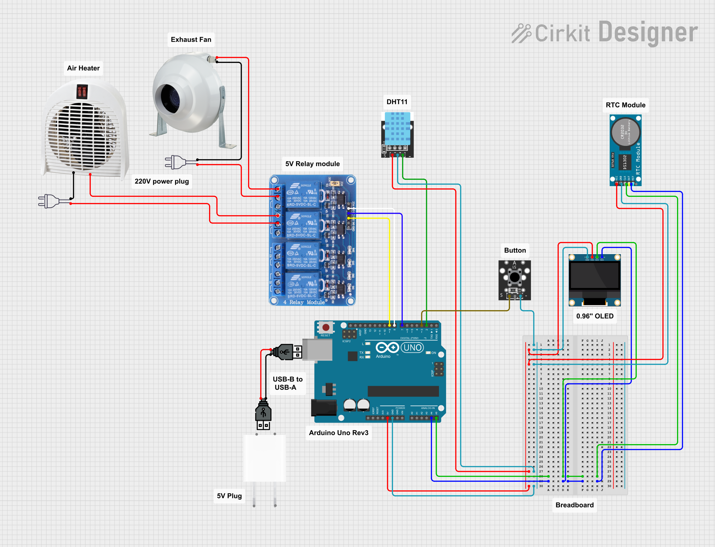
Circuit Documentation
Summary
This circuit is designed to monitor temperature and humidity using a DHT11 sensor, display the data on an OLED screen, and control an exhaust fan and air heater using a relay module. The system is powered by an Arduino UNO microcontroller, which interfaces with the various components to perform the required tasks.
Component List
KY-004 Key Switch Module
- Description: A simple key switch module used for user input.
- Pins: S, Middle, -
RTC (Real-Time Clock)
- Description: A module to keep track of the current time.
- Pins: VCC, GND, CLK, DAT, RST
KY-015 DHT11 Temperature-Humidity Sensor Module
- Description: A sensor module to measure temperature and humidity.
- Pins: VCC, GND, DOUT
0.96" OLED
- Description: A small OLED display to show data.
- Pins: GND, VDD, SCK, SDA
Exhaust Fan
- Description: A fan to control air circulation.
- Pins: L, GND
Power 220V
- Description: Power source for high voltage components.
- Pins: Hot wire, Neutral wire
Air Heater
- Description: A heater to control the temperature.
- Pins: L, GND
5V Adapter
- Description: Adapter to convert AC to 5V DC.
- Pins: AC In 1, AC In 2, 5V, GND
Arduino UNO
- Description: Microcontroller to control the circuit.
- Pins: UNUSED, IOREF, Reset, 3.3V, 5V, GND, Vin, A0, A1, A2, A3, A4, A5, SCL, SDA, AREF, D13, D12, D11, D10, D9, D8, D7, D6, D5, D4, D3, D2, D1, D0
Relay 4 Channel 5V
- Description: Relay module to control high voltage components.
- Pins: GND, IN1, IN2, IN3, IN4, VCC, COM1, COM2, COM3, COM4, NO1, NO2, NO3, NO4, NC1, NC2, NC3, NC4
USB Power
- Description: Power source for USB-powered components.
- Pins: +, -
Wiring Details
KY-004 Key Switch Module
- Pin S connected to Arduino UNO D3
- Pin - connected to GND (Common Ground)
RTC (Real-Time Clock)
- Pin VCC connected to Arduino UNO 5V
- Pin GND connected to GND (Common Ground)
- Pin CLK connected to Arduino UNO A5
- Pin DAT connected to Arduino UNO A4
KY-015 DHT11 Temperature-Humidity Sensor Module
- Pin VCC connected to Arduino UNO 5V
- Pin GND connected to GND (Common Ground)
- Pin DOUT connected to Arduino UNO D2
0.96" OLED
- Pin GND connected to GND (Common Ground)
- Pin VDD connected to Arduino UNO 5V
- Pin SCK connected to Arduino UNO A5
- Pin SDA connected to Arduino UNO A4
Exhaust Fan
- Pin L connected to Relay 4 Channel 5V NO4
- Pin GND connected to Power 220V Neutral wire
Power 220V
- Hot wire connected to Relay 4 Channel 5V COM3 and COM4
- Neutral wire connected to Exhaust Fan GND and Air Heater GND
Air Heater
- Pin L connected to Relay 4 Channel 5V NO3
- Pin GND connected to Power 220V Neutral wire
5V Adapter
- AC In 1 connected to Power 220V Hot wire
- AC In 2 connected to Power 220V Neutral wire
- 5V connected to Arduino UNO 5V
- GND connected to GND (Common Ground)
Arduino UNO
- 5V connected to VCC of RTC, KY-015 DHT11, and 0.96" OLED
- GND connected to GND (Common Ground)
- A5 connected to CLK of RTC and SCK of 0.96" OLED
- A4 connected to DAT of RTC and SDA of 0.96" OLED
- D3 connected to Pin S of KY-004 Key Switch Module
- D2 connected to DOUT of KY-015 DHT11
- D9 connected to IN2 of Relay 4 Channel 5V
- D8 connected to IN4 of Relay 4 Channel 5V
- D7 connected to IN3 of Relay 4 Channel 5V
Relay 4 Channel 5V
- IN2 connected to Arduino UNO D9
- IN4 connected to Arduino UNO D8
- IN3 connected to Arduino UNO D7
- NO4 connected to L of Exhaust Fan
- NO3 connected to L of Air Heater
- COM3 connected to Power 220V Hot wire
- COM4 connected to Power 220V Hot wire
USB Power
- Pin + connected to Pin - of another USB Power
- Pin - connected to Pin + of another USB Power
Documented Code
Arduino UNO Code (sketch.ino)
void setup() {
  // put your setup code here, to run once:

}

void loop() {
  // put your main code here, to run repeatedly:

}
Documentation (documentation.txt)
This documentation provides a comprehensive overview of the circuit, including a summary, detailed component list, wiring details, and the code used in the microcontroller.