
741 Op-Amp Signal Amplification Circuit with Oscilloscope Monitoring
View and Edit Project In Cirkit Designer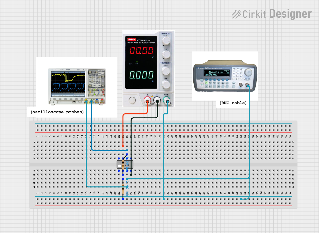
Circuit Documentation
Summary
The circuit in question appears to be a simple signal processing circuit that utilizes a 741 operational amplifier (op-amp) to amplify or manipulate a signal generated by a function generator. The signal is then observed using a mixed signal oscilloscope. The circuit is powered by a power supply and includes resistors to set the gain of the op-amp. There is no embedded code as part of this circuit since no microcontrollers are listed in the provided components.
Component List
Power Supply
- Description: Provides the necessary voltage and current to power the circuit.
- Pins: + (positive voltage), - (negative voltage), GND (ground)
Mixed Signal Oscilloscope
- Description: Used to visualize and measure the electrical signals within the circuit.
- Pins: 1, 2, 3, 4
Function Generator
- Description: Generates a variety of electrical waveforms to test and stimulate the circuit.
- Pins: sync, Output
Resistor (1 kΩ)
- Description: Provides resistance in the circuit, typically used to limit current or divide voltages.
- Value: 1000 Ohms
741 Operational Amplifier (Op-Amp)
- Description: A type of differential amplifier with high gain used for performing mathematical operations like addition, subtraction, integration, and differentiation.
- Pins: Offset Null, Inverting Input, Non-Inverting Input, V-, NC, V+, Output
Wiring Details
Power Supply
- + (positive voltage): Connected to the V+ pin of the 741 op-amp.
- - (negative voltage): Connected to the V- pin of the 741 op-amp.
- GND (ground): Connected to the Non-Inverting Input of the 741 op-amp through a resistor.
Mixed Signal Oscilloscope
- Pin 1: Connected to the Non-Inverting Input of the 741 op-amp.
- Pin 2: Connected to the Output of the 741 op-amp.
Function Generator
- Output: Connected to the Non-Inverting Input of the 741 op-amp.
Resistor (1 kΩ)
- First Resistor:
- pin1: Connected to the Inverting Input of the 741 op-amp.
- pin2: Connected to the Non-Inverting Input of the 741 op-amp and the GND of the Power Supply.
- Second Resistor:
- pin1: Connected to the Output of the 741 op-amp.
- pin2: Connected to the Inverting Input of the 741 op-amp.
741 Operational Amplifier (Op-Amp)
- V+: Connected to the + (positive voltage) of the Power Supply.
- V-: Connected to the - (negative voltage) of the Power Supply.
- Non-Inverting Input: Connected to the Output of the Function Generator, Pin 1 of the Mixed Signal Oscilloscope, and through a resistor to the GND of the Power Supply.
- Inverting Input: Connected to a resistor network forming a feedback loop with the Output.
- Output: Connected to Pin 2 of the Mixed Signal Oscilloscope and through a resistor to the Inverting Input.
Documented Code
There is no embedded code provided for this circuit as there are no microcontrollers or programmable devices listed in the components. Therefore, this section is not applicable to the current circuit documentation.