
ESP8266-Based Smart Load Cell with Bluetooth and Battery Power
View and Edit Project In Cirkit Designer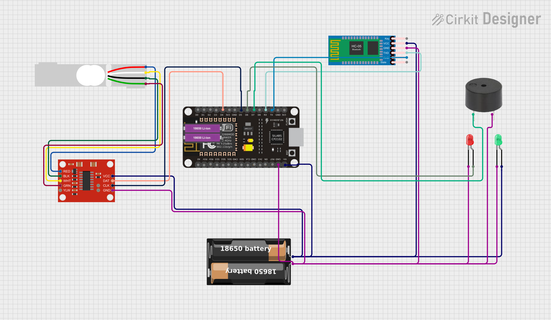
Circuit Documentation
Summary
This document provides a detailed overview of a circuit that includes an ESP8266 NodeMCU microcontroller, a load cell with an amplifier, a Bluetooth module, LEDs, a buzzer, and a battery case. The circuit is designed to interface with various sensors and actuators, providing wireless communication capabilities and visual/auditory feedback.
Component List
ESP8266 NodeMCU
- Description: A low-cost Wi-Fi microcontroller with GPIO, ADC, and other features.
- Pins: D0, D1, D2, D3, D4, 3V3, GND, D5, D6, D7, D8, RX, TX, A0, RSV, SD3, SD2, SD1, CMD, SD0, CLK, EN, RST, VIN
My Battery Case
- Description: A battery holder for two 18650 Li-ion batteries.
- Pins: +, -
18650 Li-ion Battery x 2
- Description: Rechargeable lithium-ion batteries.
- Pins: +, -
Load Cell - Red/white/black/green
- Description: A sensor to measure weight or force.
- Pins: E+, A-, E-, A+
SparkFun Load Cell Amplifier - HX711
- Description: An amplifier for load cells, providing digital output.
- Pins: GND, CLK, DAT, VCC, YLW, GRN, WHT, BLK, RED, B-, B+
HC-05 Bluetooth Module
- Description: A Bluetooth module for wireless communication.
- Pins: Key, VCC, GND, TXD, RXD, State
LED: Two Pin (green)
- Description: A green LED for visual indication.
- Pins: cathode, anode
LED: Two Pin (red)
- Description: A red LED for visual indication.
- Pins: cathode, anode
Buzzer
- Description: An audio device for sound alerts.
- Pins: PIN, GND
Wiring Details
ESP8266 NodeMCU
- D4 connected to DAT of SparkFun Load Cell Amplifier - HX711
- D5 connected to CLK of SparkFun Load Cell Amplifier - HX711
- D6 connected to anode of LED: Two Pin (red)
- D7 connected to PIN of Buzzer
- RX connected to TXD of HC-05 Bluetooth Module
- TX connected to RXD of HC-05 Bluetooth Module
- GND connected to:
- cathode of LED: Two Pin (red)
- GND of SparkFun Load Cell Amplifier - HX711
- - of My Battery Case
- GND of Buzzer
- GND of HC-05 Bluetooth Module
- cathode of LED: Two Pin (green)
- VIN connected to:
- VCC of SparkFun Load Cell Amplifier - HX711
- + of My Battery Case
- VCC of HC-05 Bluetooth Module
- anode of LED: Two Pin (green)
My Battery Case
- + connected to VIN of ESP8266 NodeMCU
- - connected to GND of ESP8266 NodeMCU
Load Cell - Red/white/black/green
- E+ connected to RED of SparkFun Load Cell Amplifier - HX711
- A- connected to WHT of SparkFun Load Cell Amplifier - HX711
- E- connected to BLK of SparkFun Load Cell Amplifier - HX711
- A+ connected to GRN of SparkFun Load Cell Amplifier - HX711
SparkFun Load Cell Amplifier - HX711
- DAT connected to D4 of ESP8266 NodeMCU
- CLK connected to D5 of ESP8266 NodeMCU
- GND connected to GND of ESP8266 NodeMCU
- VCC connected to VIN of ESP8266 NodeMCU
- RED connected to E+ of Load Cell - Red/white/black/green
- WHT connected to A- of Load Cell - Red/white/black/green
- BLK connected to E- of Load Cell - Red/white/black/green
- GRN connected to A+ of Load Cell - Red/white/black/green
HC-05 Bluetooth Module
- TXD connected to RX of ESP8266 NodeMCU
- RXD connected to TX of ESP8266 NodeMCU
- GND connected to GND of ESP8266 NodeMCU
- VCC connected to VIN of ESP8266 NodeMCU
LED: Two Pin (green)
- cathode connected to GND of ESP8266 NodeMCU
- anode connected to VIN of ESP8266 NodeMCU
LED: Two Pin (red)
- cathode connected to GND of ESP8266 NodeMCU
- anode connected to D6 of ESP8266 NodeMCU
Buzzer
- PIN connected to D7 of ESP8266 NodeMCU
- GND connected to GND of ESP8266 NodeMCU
Code
No code provided for this circuit.