
Arduino Mega 2560 and UNO-Based Dual DC Motor Control System with Wireless Joystick and Voice Recognition
View and Edit Project In Cirkit Designer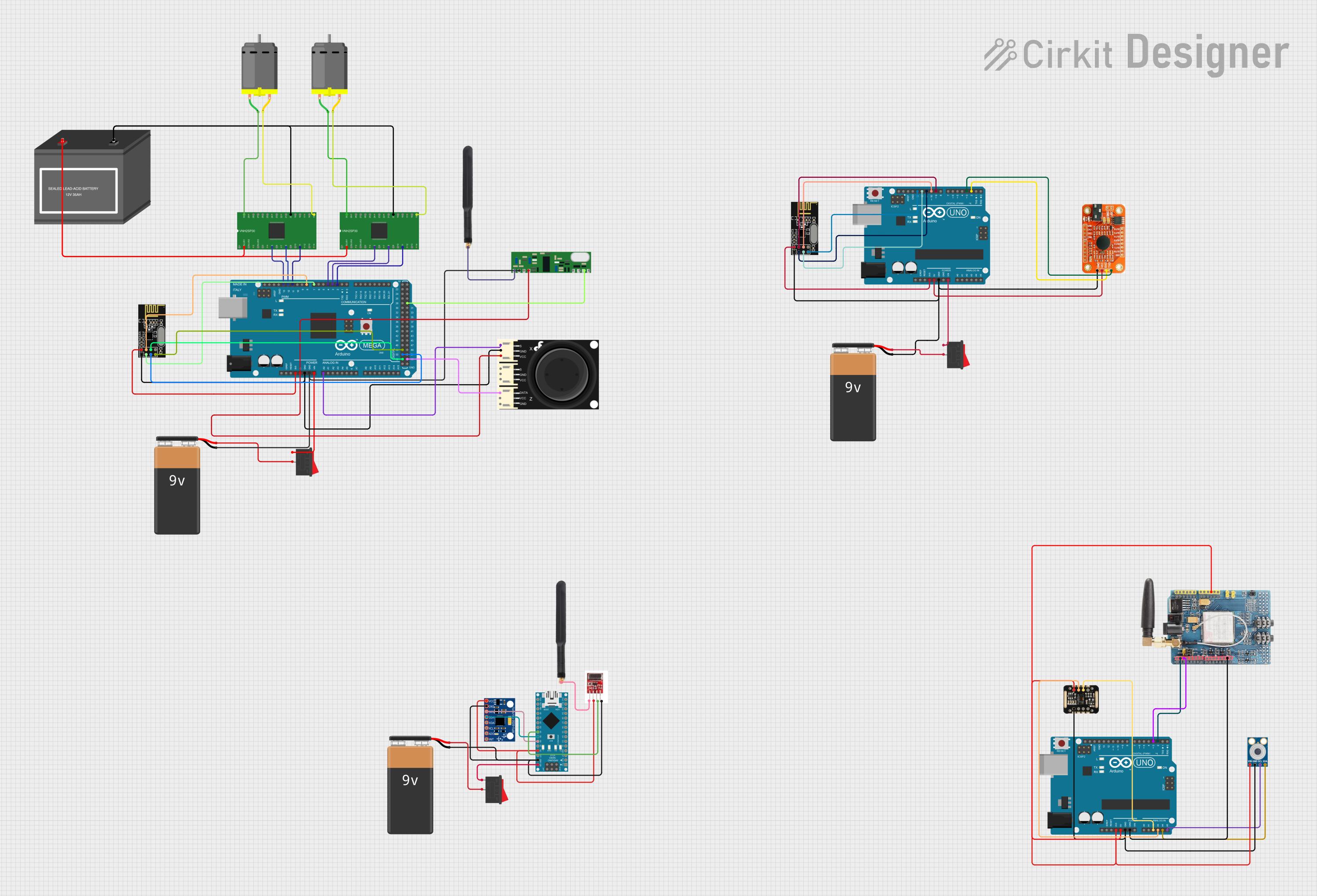
Circuit Documentation
Summary
This document provides a detailed overview of a complex circuit involving multiple microcontrollers, sensors, motors, and communication modules. The circuit is designed to perform various tasks, including motor control, wireless communication, and sensor data acquisition. The primary microcontrollers used are Arduino Mega 2560, Arduino UNO, and Arduino Nano. The circuit also includes DC motors, batteries, switches, and various sensors and communication modules.
Component List
Arduino Mega 2560
- Description: A microcontroller board based on the ATmega2560.
- Pins: IOREF, RESET, 3V3, 5V, GND, VIN, A0-A15, D0-D53, AREF, SDA, SCL
DC Motor
- Description: A simple DC motor.
- Pins: pin 1, pin 2
9V Battery
- Description: A 9V battery for power supply.
- Pins: -, +
12V Battery (mini)
- Description: A mini 12V battery for power supply.
- Pins: -, +
VNH2SP30
- Description: A high-power motor driver.
- Pins: OUTA, VCC, OUTB, GNDA, INA, EN_DIAA, PWM, CS, GNDB, EN_DIAB, INB
Rocker Switch
- Description: A simple on/off switch.
- Pins: 1, 2
NRF24L01
- Description: A 2.4GHz wireless transceiver module.
- Pins: IRQ (not used), MOSI, CSN, VCC (3V), GND, CE, SCK, MISO
Joystick Module V2
- Description: A joystick module for user input.
- Pins: Signal, Ground, VCC, DATA
Arduino UNO
- Description: A microcontroller board based on the ATmega328P.
- Pins: UNUSED, IOREF, Reset, 3.3V, 5V, GND, Vin, A0-A5, SCL, SDA, AREF, D0-D13
Voice Recognition Module
- Description: A module for voice recognition.
- Pins: GND, VCC, RDX, RTX
Arduino Nano
- Description: A small, complete, and breadboard-friendly board based on the ATmega328.
- Pins: D1/TX, D0/RX, RESET, GND, D2-D13, VIN, 5V, A0-A7, AREF, 3V3
MPU-6050
- Description: A 6-axis motion tracking device.
- Pins: VCC, GND, SCL, SDA, XDA, XCL, AD0, INT
RF Module TX
- Description: A 433MHz RF transmitter module.
- Pins: ANT, VCC, DAT, GND
RXN433MHz
- Description: A 433MHz RF receiver module.
- Pins: ANT, GND, VCC, NC, DATA
4G Antenna
- Description: A 4G antenna for wireless communication.
- Pins: Connection
GSM SIM900
- Description: A GSM module for mobile communication.
- Pins: A0-A5, 5V, GND, 3.3V, RESET, D0-D13, AREF
MLX90614
- Description: An infrared thermometer for non-contact temperature measurements.
- Pins: SDA, SCL, GND, VIN
MAX30100
- Description: A pulse oximeter and heart-rate sensor.
- Pins: VIN, SDA, SCL, GND, RD, IRD, INT
Wiring Details
Arduino Mega 2560
- 3V3 connected to NRF24L01 VCC (3V)
- 5V connected to RXN433MHz VCC and Joystick Module V2 VCC
- GND connected to NRF24L01 GND, Joystick Module V2 Ground, and RXN433MHz GND
- VIN connected to Rocker Switch 1
- A0 connected to Joystick Module V2 Signal
- D2 PWM connected to VNH2SP30 INB
- D3 PWM connected to VNH2SP30 PWM
- D4 PWM connected to VNH2SP30 INA
- D7 PWM connected to NRF24L01 CE
- D8 PWM connected to NRF24L01 CSN
- D11 PWM connected to VNH2SP30 INB
- D12 PWM connected to VNH2SP30 PWM
- D13 PWM connected to VNH2SP30 INA
- D52 connected to NRF24L01 MOSI
- D50 connected to NRF24L01 SCK
- D48 connected to NRF24L01 MISO
- D53 connected to Joystick Module V2 DATA
- D29 connected to RXN433MHz DATA
DC Motor
- pin 1 connected to VNH2SP30 OUTA
- pin 2 connected to VNH2SP30 OUTB
9V Battery
- - connected to RXN433MHz GND and Arduino Mega 2560 GND
- + connected to Rocker Switch 2
12V Battery (mini)
- - connected to VNH2SP30 GNDB
- + connected to VNH2SP30 VCC
VNH2SP30
- OUTA connected to DC Motor pin 1
- OUTB connected to DC Motor pin 2
- GNDB connected to 12V Battery (mini) -
- VCC connected to 12V Battery (mini) +
Rocker Switch
- 1 connected to Arduino Mega 2560 VIN
- 2 connected to 9V Battery +
NRF24L01
- VCC (3V) connected to Arduino Mega 2560 3V3
- GND connected to Arduino Mega 2560 GND
- CE connected to Arduino Mega 2560 D7 PWM
- CSN connected to Arduino Mega 2560 D8 PWM
- MOSI connected to Arduino Mega 2560 D52
- SCK connected to Arduino Mega 2560 D50
- MISO connected to Arduino Mega 2560 D48
Joystick Module V2
- Signal connected to Arduino Mega 2560 A0
- Ground connected to Arduino Mega 2560 GND
- VCC connected to Arduino Mega 2560 5V
- DATA connected to Arduino Mega 2560 D53
Arduino UNO
- D10 connected to NRF24L01 MOSI
- D9 connected to NRF24L01 CSN
- 3.3V connected to NRF24L01 VCC (3V)
- GND connected to 9V Battery -, Voice Recognition Module GND, and NRF24L01 GND
- D11 connected to NRF24L01 CE
- D12 connected to NRF24L01 SCK
- D13 connected to NRF24L01 MISO
- 5V connected to Voice Recognition Module VCC
- Vin connected to Rocker Switch 1
- D3 connected to Voice Recognition Module RTX
- D2 connected to Voice Recognition Module RDX
Voice Recognition Module
- GND connected to Arduino UNO GND
- VCC connected to Arduino UNO 5V
- RDX connected to Arduino UNO D2
- RTX connected to Arduino UNO D3
Arduino Nano
- VIN connected to Rocker Switch 1
- GND connected to MPU-6050 GND, 9V Battery -, and RF Module TX GND
- 5V connected to MPU-6050 VCC and RF Module TX VCC
- A6 connected to MPU-6050 SCL
- A5 connected to MPU-6050 SDA
- A4 connected to RF Module TX DAT
MPU-6050
- GND connected to Arduino Nano GND
- VCC connected to Arduino Nano 5V
- SCL connected to Arduino Nano A6
- SDA connected to Arduino Nano A5
RF Module TX
- GND connected to Arduino Nano GND
- VCC connected to Arduino Nano 5V
- **