
Arduino UNO-Based Security System with PIR Motion Detection and Bluetooth Connectivity
View and Edit Project In Cirkit Designer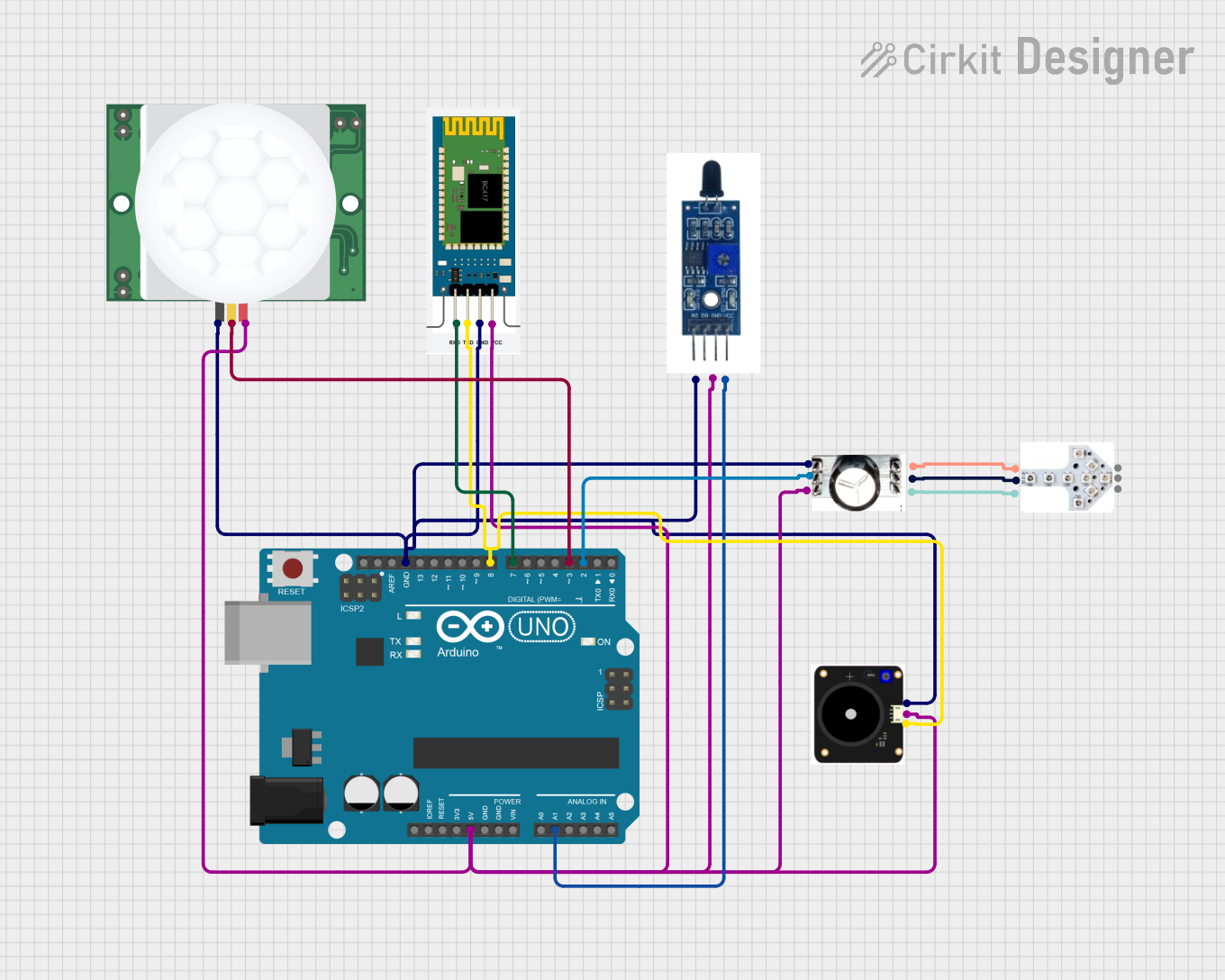
Circuit Documentation
Summary of the Circuit
This circuit is designed around the Arduino UNO platform, interfacing with various sensors and modules to perform a range of functions. The circuit includes a PIR motion sensor (PIR HC-SR501), a Bluetooth module (HC-06), an environmental sensor (FIT0449), a capacitive soil moisture sensor (SEN040129), and two LED modules (JLED-START and JLED-ARROW-9). The Arduino UNO serves as the central processing unit, reading sensor data, controlling LEDs, and communicating via Bluetooth.
Component List
Arduino UNO
- Microcontroller board based on the ATmega328P
- It has 14 digital input/output pins, 6 analog inputs, a 16 MHz quartz crystal, a USB connection, a power jack, an ICSP header, and a reset button.
PIR HC-SR501
- A passive infrared sensor that detects motion by measuring changes in the infrared levels emitted by surrounding objects.
FIT0449
- An environmental sensor capable of measuring temperature, humidity, and barometric pressure.
SEN040129
- A capacitive soil moisture sensor that measures the moisture content in soil.
HC-06
- A Bluetooth module that allows for wireless communication.
JLED-ARROW-9
- An LED module with an arrow pattern for directional indication.
JLED-START
- An LED module used to indicate the start or initiation of a process.
Wiring Details
Arduino UNO
- 5V connected to VCC of FIT0449, HC-06, JLED-START, PIR HC-SR501, SEN040129
- GND connected to GND of FIT0449, HC-06, JLED-START, PIR HC-SR501, SEN040129
- A1 connected to OUT of SEN040129
- D8 connected to TXD of HC-06
- D7 connected to RXD of HC-06
- D3 connected to SIG of PIR HC-SR501
- D2 connected to DIN of JLED-START
PIR HC-SR501
- VDD connected to 5V of Arduino UNO
- SIG connected to D3 of Arduino UNO
- GND connected to GND of Arduino UNO
FIT0449
- VCC connected to 5V of Arduino UNO
- SIGNAL connected to D8 of Arduino UNO
- GND connected to GND of Arduino UNO
SEN040129
- VCC connected to 5V of Arduino UNO
- OUT connected to A1 of Arduino UNO
- GND connected to GND of Arduino UNO
HC-06
- RXD connected to D7 of Arduino UNO
- TXD connected to D8 of Arduino UNO
- GND connected to GND of Arduino UNO
- VCC connected to 5V of Arduino UNO
JLED-ARROW-9
- DIN connected to DOUT of JLED-START
- VCC connected to VCC of JLED-START
- GND connected to GND of JLED-START
JLED-START
- DIN connected to D2 of Arduino UNO
- VCC connected to 5V of Arduino UNO
- GND connected to GND of Arduino UNO
- DOUT connected to DIN of JLED-ARROW-9
Documented Code
Arduino UNO Code (sketch.ino)
void setup() {
  // put your setup code here, to run once:

}

void loop() {
  // put your main code here, to run repeatedly:

}
Note: The provided code is a template and does not contain any functional code. It is expected that the user will fill in the setup and loop functions with code to initialize the components and define the main behavior of the circuit.