
Arduino Mega 2560-Based PWM Fan and LED Strip Controller with Potentiometer Adjustment
View and Edit Project In Cirkit Designer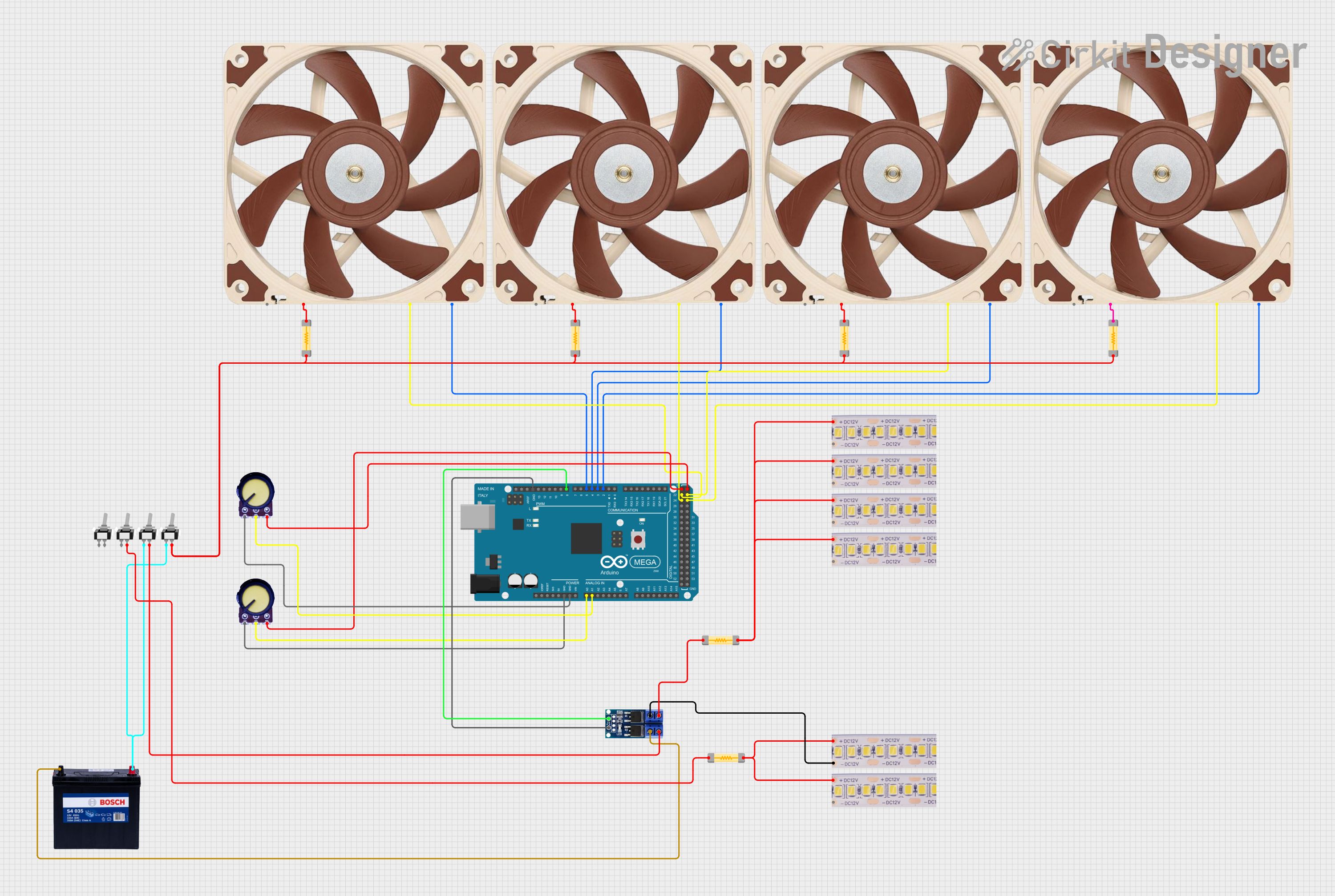
Circuit Documentation
Summary
This circuit is designed to control four PWM fans and a 12V white LED strip using an Arduino Mega 2560. The fan speeds and LED brightness are controlled by two potentiometers. The circuit also includes a motor driver and several fuses for protection.
Component List
Arduino Mega 2560
- Description: Microcontroller board based on the ATmega2560.
- Pins: IOREF, RESET, 3V3, 5V, GND, VIN, A0-A15, D0-D53, AREF, SDA, SCL
Potentiometer
- Description: Variable resistor used to control fan speed and LED brightness.
- Pins: GND, Output, VCC
12V PWM Fan (120mm)
- Description: 120mm fan with PWM control.
- Pins: GND, +12V, TACH, PWM
12V White LED strip
- Description: LED strip powered by 12V.
- Pins: +12V, GND
Toggle Switch SPST
- Description: Single-pole single-throw switch.
- Pins: L1, COM
5A Fuse
- Description: Fuse rated at 5A for circuit protection.
- Pins: 1, 2
12V 200Ah Battery
- Description: 12V battery for powering the circuit.
- Pins: GND, 12V
Motor Driver - N-Mos PWM Trigger
- Description: Motor driver for controlling the LED strip.
- Pins: + PWM, GND, OUT -, OUT +, DC OUT +, DC IN -
Wiring Details
Arduino Mega 2560
- GND: Connected to GND of both potentiometers and the motor driver.
- A0: Connected to the Output of the first potentiometer.
- A1: Connected to the Output of the second potentiometer.
- D2 PWM: Connected to the PWM pin of the first fan.
- D3 PWM: Connected to the PWM pin of the second fan.
- D4 PWM: Connected to the PWM pin of the third fan.
- D5 PWM: Connected to the PWM pin of the fourth fan.
- D8 PWM: Connected to the + PWM pin of the motor driver.
- D22: Connected to the TACH pin of the second fan.
- D23: Connected to the TACH pin of the fourth fan.
- D24: Connected to the TACH pin of the third fan.
- D25: Connected to the TACH pin of the first fan.
- 5V: Connected to VCC of both potentiometers.
Potentiometer (Fan Control)
- GND: Connected to GND of the Arduino.
- Output: Connected to A0 of the Arduino.
- VCC: Connected to 5V of the Arduino.
Potentiometer (LED Control)
- GND: Connected to GND of the Arduino.
- Output: Connected to A1 of the Arduino.
- VCC: Connected to 5V of the Arduino.
12V PWM Fan (120mm)
- GND: Connected to the GND of the 12V battery.
- +12V: Connected to the 12V battery through a 5A fuse.
- TACH: Connected to D22, D23, D24, and D25 of the Arduino.
- PWM: Connected to D2, D3, D4, and D5 of the Arduino.
12V White LED strip
- +12V: Connected to the 12V battery through a 5A fuse.
- GND: Connected to the OUT - pin of the motor driver.
Toggle Switch SPST
- L1: Connected to the 12V pin of the battery.
- COM: Connected to the DC OUT + pin of the motor driver and the 5A fuse.
5A Fuse
- 1: Connected to the +12V pin of the fans and LED strip.
- 2: Connected to the COM pin of the toggle switch.
12V 200Ah Battery
- GND: Connected to the GND of the motor driver.
- 12V: Connected to the L1 pin of the toggle switch.
Motor Driver - N-Mos PWM Trigger
- + PWM: Connected to D8 PWM of the Arduino.
- GND: Connected to the GND of the Arduino.
- OUT -: Connected to the GND of the LED strip.
- OUT +: Connected to the 5A fuse.
- DC OUT +: Connected to the COM pin of the toggle switch.
- DC IN -: Connected to the GND of the 12V battery.
Code Documentation
/*
 * This Arduino sketch controls four PWM fans and an LED strip.
 * Fan speeds are controlled by a potentiometer connected to A0.
 * LED brightness is controlled by a potentiometer connected to A1.
 */

// Pin definitions
const int fan1PWM = 2;
const int fan2PWM = 3;
const int fan3PWM = 4;
const int fan4PWM = 5;
const int ledPWM = 8;
const int potFan = A0;
const int potLED = A1;

void setup() {
  // Initialize PWM pins as outputs
  pinMode(fan1PWM, OUTPUT);
  pinMode(fan2PWM, OUTPUT);
  pinMode(fan3PWM, OUTPUT);
  pinMode(fan4PWM, OUTPUT);
  pinMode(ledPWM, OUTPUT);
  // Initialize serial communication for debugging
  Serial.begin(9600);
}

void loop() {
  // Read potentiometer values
  int potFanValue = analogRead(potFan);
  int potLEDValue = analogRead(potLED);
  // Map potentiometer values to PWM range (0-255)
  int fanSpeed = map(potFanValue, 0, 1023, 0, 255);
  int ledBrightness = map(potLEDValue, 0, 1023, 0, 255);
  // Set fan speeds
  analogWrite(fan1PWM, fanSpeed);
  analogWrite(fan2PWM, fanSpeed);
  analogWrite(fan3PWM, fanSpeed);
  analogWrite(fan4PWM, fanSpeed);
  // Set LED brightness
  analogWrite(ledPWM, ledBrightness);
  // Print values for debugging
  Serial.print("Fan Speed: ");
  Serial.print(fanSpeed);
  Serial.print("\tLED Brightness: ");
  Serial.println(ledBrightness);
  // Small delay to stabilize readings
  delay(100);
}
This code initializes the PWM pins for the fans and LED strip as outputs. It reads the values from the potentiometers connected to A0 and A1, maps these values to the PWM range (0-255), and sets the fan speeds and LED brightness accordingly. The values are also printed to the serial monitor for debugging purposes.