Cirkit Designer
Your all-in-one circuit design IDE
Home /
Project Documentation
Bluetooth-Controlled Robotic Car with L293D Motor Driver and LED Indicators

Circuit Documentation
Summary
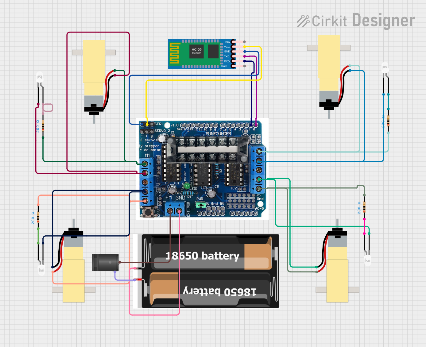
This document provides a detailed overview of a circuit that includes a motor driver shield, Bluetooth module, gear motors, LEDs, resistors, a battery pack, and a DC barrel jack. The circuit is designed to control multiple gear motors and LEDs, with power supplied by a battery pack and a DC barrel jack. The Bluetooth module allows for wireless communication.
Component List
L293D Driver Shield
- Description: Motor driver shield capable of driving multiple motors.
- Pins: 5v, GND, A0, A1, A2, A3, A4, A5, M+, M2, M1, M3, M4, 0, 1, 2, 3, 4, 5, 6, 7, 8, 9, 10, 11, 12, gnd, Aref, ser1, Servo2, +, -, 9v
HC-05 Bluetooth Module
- Description: Bluetooth module for wireless communication.
- Pins: Key, VCC, TXD, RXD, State, GND
Hobby Gearmotor with 48:1 Gearbox
- Description: Gear motor with a 48:1 gearbox.
- Pins: pin 1, pin 2
LED: Two Pin (white)
- Description: White LED with two pins.
- Pins: cathode, anode
Resistor
- Description: Resistor with a resistance of 200 Ohms.
- Pins: pin1, pin2
2x 18650 Battery Pack
- Description: Battery pack containing two 18650 batteries.
- Pins: vcc, gnd
Terminal Block KTB1 20A 6P
- Description: Terminal block for connecting multiple wires.
- Pins: 1, 2, 4, 5, 6, 3
2.1mm DC Barrel Jack
- Description: DC barrel jack for power input.
- Pins: switch, sleeve, center
Wiring Details
L293D Driver Shield
- M+ is connected to center of the 2.1mm DC Barrel Jack.
- GND is connected to gnd of the 2x 18650 Battery Pack.
- M2 is connected to pin 1 of the Hobby Gearmotor with 48:1 Gearbox and cathode of the LED.
- M2 is connected to pin 2 of the Hobby Gearmotor with 48:1 Gearbox and pin2 of the Resistor.
- M1 is connected to pin 1 of the Hobby Gearmotor with 48:1 Gearbox and cathode of the LED.
- M1 is connected to pin 2 of the Hobby Gearmotor with 48:1 Gearbox and pin1 of the Resistor.
- M3 is connected to pin 1 of the Hobby Gearmotor with 48:1 Gearbox and cathode of the LED.
- M3 is connected to pin 2 of the Hobby Gearmotor with 48:1 Gearbox and pin2 of the Resistor.
- M4 is connected to pin 1 of the Hobby Gearmotor with 48:1 Gearbox and cathode of the LED.
- M4 is connected to pin 2 of the Hobby Gearmotor with 48:1 Gearbox and pin1 of the Resistor.
- 0 is connected to TXD of the HC-05 Bluetooth Module.
- 1 is connected to RXD of the HC-05 Bluetooth Module.
- + is connected to VCC of the HC-05 Bluetooth Module.
- - is connected to GND of the HC-05 Bluetooth Module.
HC-05 Bluetooth Module
- TXD is connected to 0 of the L293D Driver Shield.
- RXD is connected to 1 of the L293D Driver Shield.
- VCC is connected to + of the L293D Driver Shield.
- GND is connected to - of the L293D Driver Shield.
Hobby Gearmotor with 48:1 Gearbox
- pin 1 is connected to M2 of the L293D Driver Shield and cathode of the LED.
- pin 2 is connected to M2 of the L293D Driver Shield and pin2 of the Resistor.
- pin 1 is connected to M1 of the L293D Driver Shield and cathode of the LED.
- pin 2 is connected to M1 of the L293D Driver Shield and pin1 of the Resistor.
- pin 1 is connected to M3 of the L293D Driver Shield and cathode of the LED.
- pin 2 is connected to M3 of the L293D Driver Shield and pin2 of the Resistor.
- pin 1 is connected to M4 of the L293D Driver Shield and cathode of the LED.
- pin 2 is connected to M4 of the L293D Driver Shield and pin1 of the Resistor.
LED: Two Pin (white)
- cathode is connected to M2 of the L293D Driver Shield and pin 1 of the Hobby Gearmotor with 48:1 Gearbox.
- anode is connected to pin2 of the Resistor.
- cathode is connected to M1 of the L293D Driver Shield and pin 1 of the Hobby Gearmotor with 48:1 Gearbox.
- anode is connected to pin2 of the Resistor.
- cathode is connected to M3 of the L293D Driver Shield and pin 1 of the Hobby Gearmotor with 48:1 Gearbox.
- anode is connected to pin2 of the Resistor.
- cathode is connected to M4 of the L293D Driver Shield and pin 1 of the Hobby Gearmotor with 48:1 Gearbox.
- anode is connected to pin2 of the Resistor.
Resistor
- pin1 is connected to M1 of the L293D Driver Shield and pin 2 of the Hobby Gearmotor with 48:1 Gearbox.
- pin2 is connected to anode of the LED.
- pin1 is connected to M2 of the L293D Driver Shield and pin 2 of the Hobby Gearmotor with 48:1 Gearbox.
- pin2 is connected to anode of the LED.
- pin1 is connected to M3 of the L293D Driver Shield and pin 2 of the Hobby Gearmotor with 48:1 Gearbox.
- pin2 is connected to anode of the LED.
- pin1 is connected to M4 of the L293D Driver Shield and pin 2 of the Hobby Gearmotor with 48:1 Gearbox.
- pin2 is connected to anode of the LED.
2x 18650 Battery Pack
- vcc is connected to sleeve of the 2.1mm DC Barrel Jack.
- gnd is connected to GND of the L293D Driver Shield.
2.1mm DC Barrel Jack
- center is connected to M+ of the L293D Driver Shield.
- sleeve is connected to vcc of the 2x 18650 Battery Pack.
Code
No code is provided for this circuit.