
Arduino-Controlled RFID Door Lock with Status Indicator LEDs
View and Edit Project In Cirkit Designer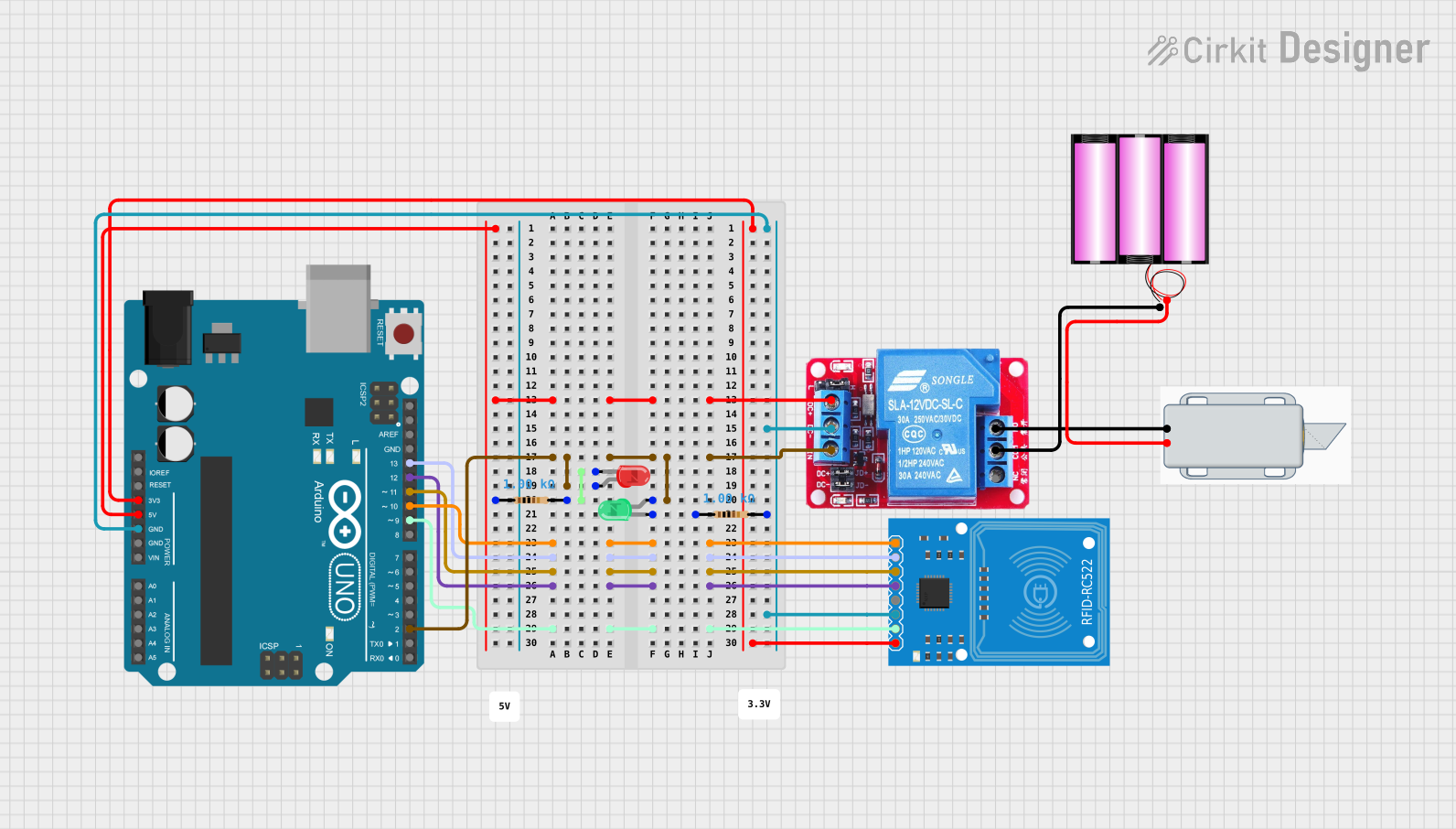
Circuit Documentation
Summary
This circuit is designed to interface an RFID-RC522 module with an Arduino UNO for identification purposes. The circuit includes a 12V relay to control a solenoid lock, indicating the access status with a red and green LED. The RFID reader is powered by the 3.3V output from the Arduino, while the relay and solenoid lock are powered by a separate 12V battery. The relay is controlled by a digital output from the Arduino, which also drives the LEDs through current-limiting resistors.
Component List
RFID-RC522
- Description: RFID reader/writer module for 13.56MHz cards.
- Pins: SDA, SCK, MOSI, MISO, IRQ, GND, RST, 3.3V
12V Relay
- Description: Electromechanical switch used to control the solenoid lock.
- Pins: NO, COM, NC, DC+, DC-, IN
12V Solenoid Lock
- Description: Electric lock that is actuated by the relay.
- Pins: -, +
Arduino UNO
- Description: Microcontroller board based on the ATmega328P.
- Pins: UNUSED, IOREF, Reset, 3.3V, 5V, GND, Vin, A0-A5, SCL, SDA, AREF, D0-D13
LED: Two Pin (green)
- Description: Green LED used to indicate access granted.
- Pins: cathode, anode
LED: Two Pin (red)
- Description: Red LED used to indicate access denied or standby.
- Pins: cathode, anode
Resistor (1k Ohm)
- Description: Current-limiting resistor for the LEDs.
- Value: 1000 Ohms
Battery 12V
- Description: Power source for the relay and solenoid lock.
- Pins: +, -
Wiring Details
RFID-RC522
- SDA connected to Arduino UNO D10
- SCK connected to Arduino UNO D13
- MOSI connected to Arduino UNO D11
- MISO connected to Arduino UNO D12
- IRQ not connected
- GND connected to Arduino UNO GND
- RST connected to Arduino UNO D9
- 3.3V connected to Arduino UNO 3.3V
12V Relay
- NO connected to 12V Solenoid Lock +
- COM connected to Battery 12V -
- NC not used
- DC+ connected to Arduino UNO 5V through a 1k Ohm resistor
- DC- connected to Arduino UNO GND
- IN connected to Arduino UNO D2
12V Solenoid Lock
-
- connected to 12V Relay NO
-
- connected to Battery 12V +
Arduino UNO
- 5V connected to 12V Relay DC+ through a 1k Ohm resistor
- 3.3V connected to RFID-RC522 3.3V
- GND connected to RFID-RC522 GND, 12V Relay DC-, and both LED cathodes through 1k Ohm resistors
- D2 connected to 12V Relay IN
- D10 connected to RFID-RC522 SDA
- D11 connected to RFID-RC522 MOSI
- D12 connected to RFID-RC522 MISO
- D13 connected to RFID-RC522 SCK
- D9 connected to RFID-RC522 RST
LED: Two Pin (green)
- anode connected to Arduino UNO D2
- cathode connected to GND through a 1k Ohm resistor
LED: Two Pin (red)
- anode connected to Arduino UNO D2
- cathode connected to GND through a 1k Ohm resistor
Resistor (1k Ohm)
- One resistor connected between Arduino UNO 5V and 12V Relay DC+
- One resistor connected between Arduino UNO GND and each LED cathode
Battery 12V
-
- connected to 12V Solenoid Lock +
-
- connected to 12V Relay COM
Documented Code
void setup() {
  // put your setup code here, to run once:

}

void loop() {
  // put your main code here, to run repeatedly:

}
Filename: sketch.ino
The provided code is a template and does not include any functionality. It needs to be populated with the setup configurations for the pins and the main logic to interact with the RFID module, control the relay, and update the status LEDs.