
ESP32-CAM Controlled Security System with Solenoid Lock and Indicator LEDs
View and Edit Project In Cirkit Designer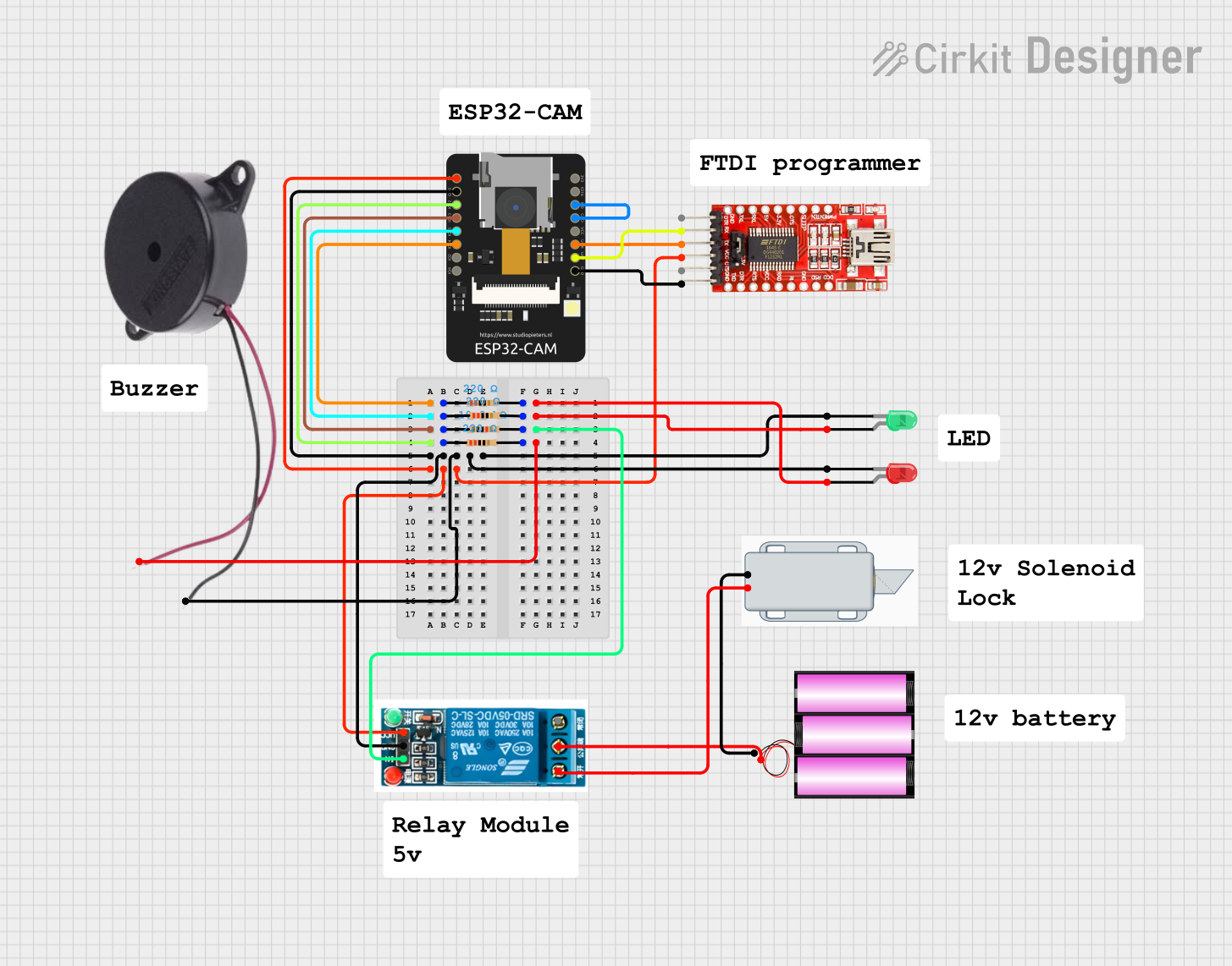
Circuit Documentation
Summary
This circuit is designed to control various components including LEDs, a solenoid lock, a buzzer, and a relay using an ESP32-CAM microcontroller. The ESP32-CAM is interfaced with an FTDI programmer for programming and serial communication. The circuit includes resistors for current limiting and pull-up configurations. The 12V solenoid lock is controlled via a 5V relay, which is in turn controlled by the ESP32-CAM. The LEDs and buzzer are directly controlled by the ESP32-CAM through GPIO pins with appropriate current-limiting resistors.
Component List
LEDs
- Green LED: A two-pin green LED used for indication purposes.
- Red LED: A two-pin red LED used for indication purposes.
Solenoid Lock
- 12V Solenoid Lock: An electromechanical lock that is actuated by a 12V supply.
Resistors
- 10k Ohm Resistor: Used for pull-up or pull-down purposes to ensure a known state for a signal line.
- 220 Ohm Resistors: Three resistors used to limit current to the LEDs and buzzer.
Microcontroller
- ESP32-CAM: A WiFi and Bluetooth enabled microcontroller with camera support, used as the main controller for the circuit.
Programmer
- FTDI Programmer: Used to program the ESP32-CAM and provide serial communication.
Buzzer
- Buzzer: An audible signaling device.
Relay
- 5V Relay: An electromechanical switch used to control the solenoid lock with the ESP32-CAM.
Power Sources
- Battery 12V: Provides power to the solenoid lock.
Wiring Details
Green LED
- Anode: Connected to GPIO15 of the ESP32-CAM through a 220 Ohm resistor.
- Cathode: Connected to the common ground.
Red LED
- Anode: Connected to GPIO14 of the ESP32-CAM through a 220 Ohm resistor.
- Cathode: Connected to the common ground.
12V Solenoid Lock
- +: Connected to the Normally Open pin of the 5V relay.
- -: Connected to the negative terminal of the 12V battery.
Resistors
- 10k Ohm Resistor: One end connected to GPIO13 of the ESP32-CAM, the other end to the In pin of the 5V relay.
- 220 Ohm Resistors: Each connected between a GPIO pin of the ESP32-CAM and the anode of an LED or the positive pin of the buzzer.
ESP32-CAM
- 5V: Connected to the VCC of the FTDI Programmer and the 5V relay.
- GND: Common ground for the circuit.
- IO12, IO13, IO14, IO15: Connected to various components through resistors as control signals.
- IO0: Connected to GND for programming mode.
- VOT (TX): Connected to the RX pin of the FTDI Programmer.
- VOR (RX): Connected to the TX pin of the FTDI Programmer.
FTDI Programmer
- VCC: Connected to the 5V supply of the ESP32-CAM and the 5V relay.
- GND: Connected to the common ground.
- RX: Connected to the TX pin of the ESP32-CAM.
- TX: Connected to the RX pin of the ESP32-CAM.
Buzzer
- POSITIVE: Connected to GPIO12 of the ESP32-CAM through a 220 Ohm resistor.
- NEGATIVE: Connected to the common ground.
5V Relay
- In: Connected to GPIO13 of the ESP32-CAM through a 10k Ohm resistor.
- GND: Connected to the common ground.
- VCC: Connected to the 5V supply from the FTDI Programmer.
- Normally Open: Connected to the positive terminal of the solenoid lock.
- Common terminal: Connected to the positive terminal of the 12V battery.
Battery 12V
- +: Connected to the Common terminal of the 5V relay.
- -: Connected to the negative terminal of the solenoid lock.
Documented Code
No code was provided for the microcontroller. The documentation of the code would typically include a description of the functionality, setup and loop functions, and any functions or libraries used to control the peripherals. Since no code is available, this section cannot be completed.