
Arduino UNO-Based Smart Lock System with Fingerprint and Voice Recognition
View and Edit Project In Cirkit Designer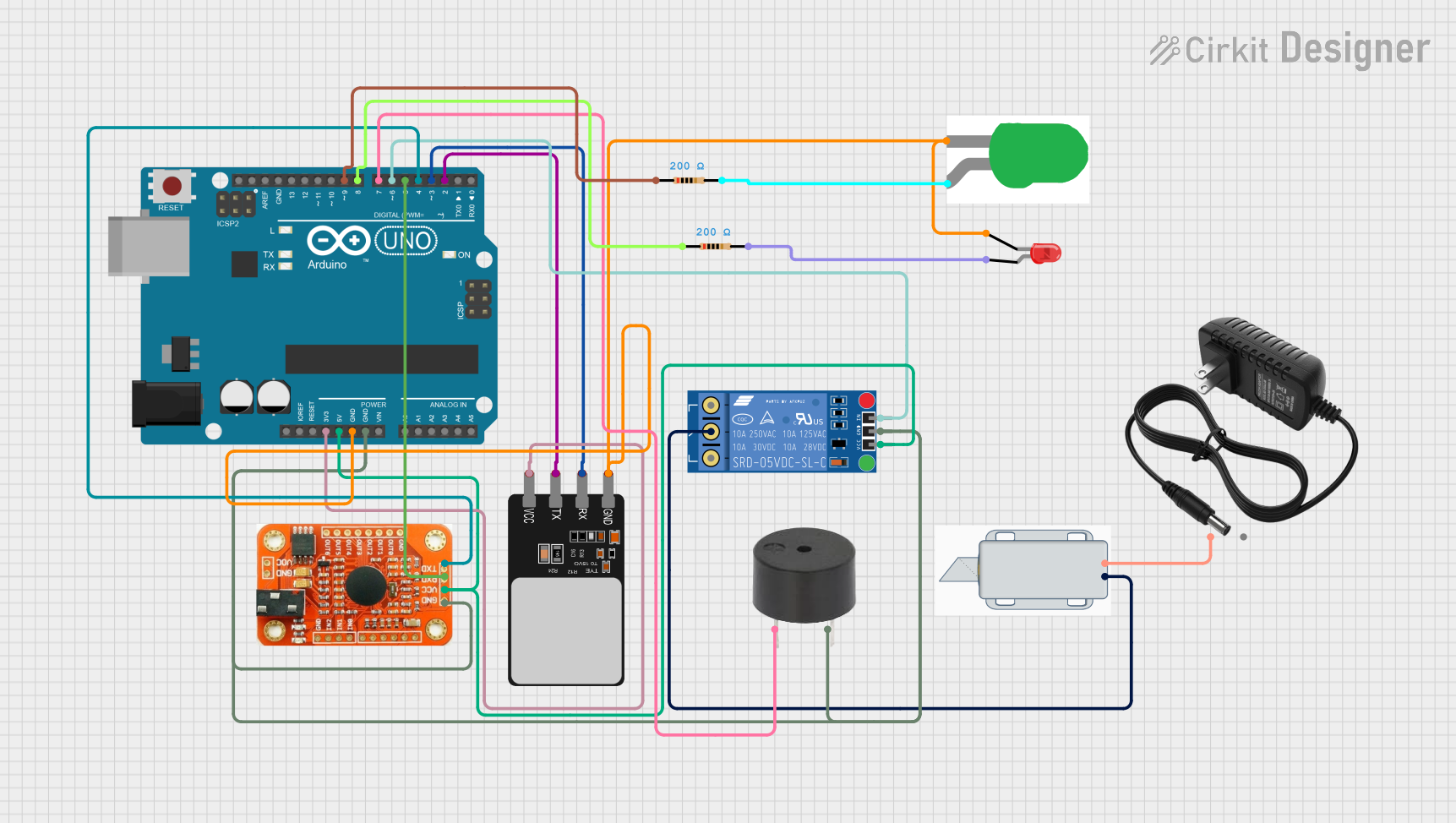
Circuit Documentation
Summary
This circuit integrates an Arduino UNO microcontroller with various peripherals including a fingerprint scanner, a voice recognition module, a relay, a buzzer, LEDs, resistors, a solenoid lock, and a 12V power supply. The system is designed to control a solenoid lock based on inputs from the fingerprint scanner and voice recognition module, with visual and auditory feedback provided by LEDs and a buzzer.
Component List
Arduino UNO
- Description: A microcontroller board based on the ATmega328P.
- Pins: UNUSED, IOREF, Reset, 3.3V, 5V, GND, Vin, A0, A1, A2, A3, A4, A5, SCL, SDA, AREF, D13, D12, D11, D10, D9, D8, D7, D6, D5, D4, D3, D2, D1, D0
Fingerprint Scanner
- Description: A biometric sensor for fingerprint recognition.
- Pins: VCC, TX, RX, GND
Voice Recognition Module
- Description: A module for recognizing voice commands.
- Pins: GND, VCC, RDX, RTX
KF-301 Relay
- Description: A relay module for switching high-power devices.
- Pins: signal, power, ground, NC, C, NO
Buzzer
- Description: An audio signaling device.
- Pins: PIN, GND
LED: Two Pin (green)
- Description: A green LED for visual indication.
- Pins: cathode, anode
LED: Two Pin (red)
- Description: A red LED for visual indication.
- Pins: cathode, anode
12V Power Supply
- Description: A power supply providing 12V DC.
- Pins: +, -
Resistor (200 Ohms)
- Description: A resistor with a resistance of 200 Ohms.
- Pins: pin1, pin2
12V Solenoid Lock
- Description: An electromechanical lock that operates on 12V.
- Pins: -, +
Wiring Details
Arduino UNO
- 3.3V connected to VCC of Fingerprint Scanner
- 5V connected to power of KF-301 Relay and VCC of Voice Recognition Module
- GND connected to GND of Fingerprint Scanner, cathode of red LED, cathode of green LED, GND of Buzzer, ground of KF-301 Relay, and GND of Voice Recognition Module
- D9 connected to pin1 of Resistor (200 Ohms)
- D8 connected to pin1 of Resistor (200 Ohms)
- D7 connected to PIN of Buzzer
- D6 connected to signal of KF-301 Relay
- D5 connected to RDX of Voice Recognition Module
- D4 connected to RTX of Voice Recognition Module
- D3 connected to RX of Fingerprint Scanner
- D2 connected to TX of Fingerprint Scanner
Fingerprint Scanner
- VCC connected to 3.3V of Arduino UNO
- TX connected to D2 of Arduino UNO
- RX connected to D3 of Arduino UNO
- GND connected to GND of Arduino UNO
Voice Recognition Module
- VCC connected to 5V of Arduino UNO
- RDX connected to D5 of Arduino UNO
- RTX connected to D4 of Arduino UNO
- GND connected to GND of Arduino UNO
KF-301 Relay
- signal connected to D6 of Arduino UNO
- power connected to 5V of Arduino UNO
- ground connected to GND of Arduino UNO
- C connected to - of 12V Solenoid Lock
Buzzer
- PIN connected to D7 of Arduino UNO
- GND connected to GND of Arduino UNO
LED: Two Pin (green)
- cathode connected to GND of Arduino UNO
- anode connected to pin2 of Resistor (200 Ohms)
LED: Two Pin (red)
- cathode connected to GND of Arduino UNO
- anode connected to pin2 of Resistor (200 Ohms)
12V Power Supply
- + connected to + of 12V Solenoid Lock
Resistor (200 Ohms)
- pin1 connected to D9 of Arduino UNO
- pin2 connected to anode of green LED
Resistor (200 Ohms)
- pin1 connected to D8 of Arduino UNO
- pin2 connected to anode of red LED
12V Solenoid Lock
- - connected to C of KF-301 Relay
- + connected to + of 12V Power Supply
Code Documentation
Arduino UNO Code
void setup() {
  // put your setup code here, to run once:

}

void loop() {
  // put your main code here, to run repeatedly:

}
This code is a basic template for the Arduino UNO. The setup() function is where you initialize your components and settings, and the loop() function is where the main logic of your program runs repeatedly.