
ESP8266 NodeMCU Controlled 4-Channel Relay for Smart Lighting
View and Edit Project In Cirkit Designer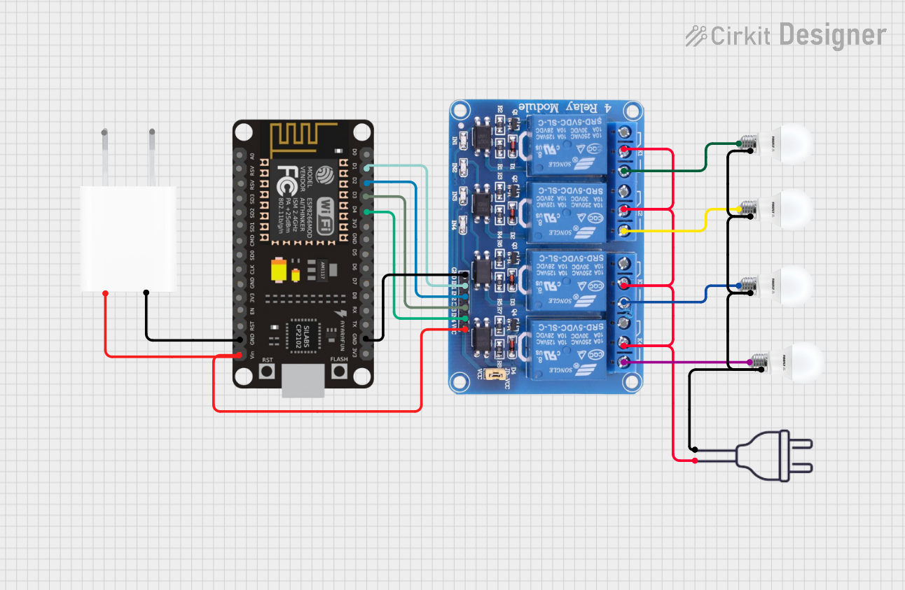
Circuit Documentation
Summary
This circuit is designed to control four individual bulbs using an ESP8266 NodeMCU microcontroller and a 4-channel 5V relay module. The ESP8266 NodeMCU is responsible for triggering the relays, which in turn switch the bulbs on and off. The relay module is powered by a 5V adapter, and the bulbs are powered by a 220V power source. The ground connections are shared among the components to complete the circuit.
Component List
ESP8266 NodeMCU
- Description: A Wi-Fi capable microcontroller module based on the ESP8266 chip.
- Pins: D0, D1, D2, D3, D4, 3V3, GND, D5, D6, D7, D8, RX, TX, A0, RSV, SD3, SD2, SD1, CMD, SD0, CLK, EN, RST, VIN
Relay 4 Channel 5V
- Description: A relay module with four channels that can be controlled independently to switch external circuits.
- Pins: GND, IN1, IN2, IN3, IN4, VCC, COM1, COM2, COM3, COM4, NO1, NO2, NO3, NO4, NC1, NC2, NC3, NC4
5V Adapter
- Description: A power adapter that converts AC voltage to a 5V DC output.
- Pins: AC In 1, AC In 2, 5V, GND
Bulb
- Description: A standard electric bulb that operates at 220V.
- Pins: +, -
Power 220V
- Description: A power source providing 220V AC.
- Pins: Hot wire, Neutral wire
Wiring Details
ESP8266 NodeMCU
- D1 - Connected to Relay 4 Channel 5V IN1
- D2 - Connected to Relay 4 Channel 5V IN2
- D3 - Connected to Relay 4 Channel 5V IN3
- D4 - Connected to Relay 4 Channel 5V IN4
- GND - Shared ground with 5V Adapter and Relay 4 Channel 5V
- VIN - Connected to 5V output from the 5V Adapter
Relay 4 Channel 5V
- GND - Shared ground with ESP8266 NodeMCU
- IN1, IN2, IN3, IN4 - Controlled by ESP8266 NodeMCU D1, D2, D3, D4 respectively
- VCC - Connected to 5V output from the 5V Adapter
- COM1, COM2, COM3, COM4 - Connected to Neutral wire from Power 220V
- NO1, NO2, NO3, NO4 - Connected to the positive (+) pin of each Bulb
5V Adapter
- GND - Shared ground with ESP8266 NodeMCU
- 5V - Connected to VIN of ESP8266 NodeMCU and VCC of Relay 4 Channel 5V
Bulb
- + - Connected to the corresponding NO pin on the Relay 4 Channel 5V
- - - Connected to the Hot wire from Power 220V
Power 220V
- Neutral wire - Connected to COM pins on Relay 4 Channel 5V
- Hot wire - Connected to the negative (-) pin of each Bulb
Documented Code
No code has been provided for the ESP8266 NodeMCU. The expected functionality would include initializing the GPIO pins connected to the relay module and toggling them to control the state of the bulbs. Without the code, we cannot document the specific implementation details or provide a code walkthrough.