Arduino Mega 2560 Controlled Multi-Motor Drive System
Circuit Documentation
Summary
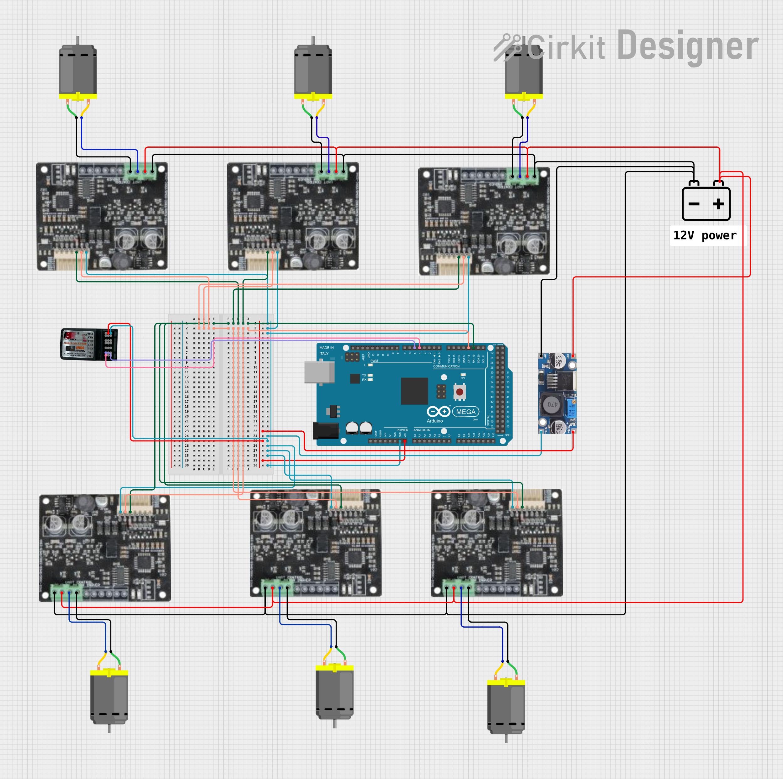
This circuit is designed to control multiple DC motors using an Arduino Mega 2560 as the central processing unit. The Arduino interfaces with multiple motor drives, which in turn control the DC motors. A step-down buck converter is used to regulate the voltage from a 12V battery to a lower voltage suitable for the motor drives and the Arduino. An FS-CT6B receiver is included to receive control signals, presumably for remote operation. The circuit appears to be part of a system that requires multiple motors to be controlled, possibly for a robotic or vehicular application.
Component List
Arduino Mega 2560
- Microcontroller board based on the ATmega2560
- It has 54 digital input/output pins (of which 15 can be used as PWM outputs), 16 analog inputs, 4 UARTs (hardware serial ports), a 16 MHz crystal oscillator, a USB connection, a power jack, an ICSP header, and a reset button.
Motor Drives
- Interface between the microcontroller and the motors
- Each drive has connections for motor power (motor -v, motor +v), logic power (VDD), ground (GND), and serial communication (RXD, TXD).
FS-CT6B Receiver
- A 6-channel radio receiver commonly used for remote control applications in models and drones.
- It has channels for binding and power, as well as signal outputs for up to 6 channels.
DC Motors
- Standard DC motors with two connections (pin 1, pin 2) for power input.
12V Battery
- Provides the main power source for the circuit.
Step-Down Buck Converter
- Converts the higher voltage from the battery to a lower voltage suitable for the electronics.
Wiring Details
Arduino Mega 2560
- VIN connected to the output of the step-down buck converter to power the board.
- GND connected to the common ground net.
- D19/RX1 connected to the TXD pins of all motor drives for serial communication.
- D18/TX1 connected to the RXD pins of all motor drives for serial communication.
- D4 PWM connected to channel 1 of the FS-CT6B Receiver.
- D5 PWM connected to channel 2 of the FS-CT6B Receiver.
Motor Drives
- motor -v and motor +v connected to the corresponding pins of the DC motors to control their operation.
- VDD connected to the positive terminal of the 12V battery through the step-down buck converter.
- GND connected to the common ground net.
- RXD and TXD connected to the Arduino Mega 2560 for serial communication.
FS-CT6B Receiver
- +ve connected to the output of the step-down buck converter to power the receiver.
- -ve connected to the common ground net.
- Channels 1 and 2 connected to the Arduino Mega 2560 for control signal input.
DC Motors
- pin 1 connected to the motor -v of the corresponding motor drive.
- pin 2 connected to the motor +v of the corresponding motor drive.
12V Battery
- + connected to the input of the step-down buck converter to supply power.
- - connected to the common ground net.
Step-Down Buck Converter
- IN + connected to the positive terminal of the 12V battery.
- IN - GND connected to the common ground net.
- OUT + connected to the VIN of the Arduino Mega 2560 and the +ve of the FS-CT6B Receiver.
- OUT - GND connected to the common ground net.
Documented Code
Arduino Mega 2560
File: sketch.ino
void setup() {
  // put your setup code here, to run once:

}

void loop() {
  // put your main code here, to run repeatedly:

}
File: documentation.txt
(No additional documentation provided for the code)
(Note: The provided code is a template and does not contain any functional code for controlling the motors or interfacing with the receiver. Additional code would be required to implement the desired functionality.)