Arduino-Controlled IR Sensor and Servo Motor Obstacle Interaction
Circuit Documentation
Summary
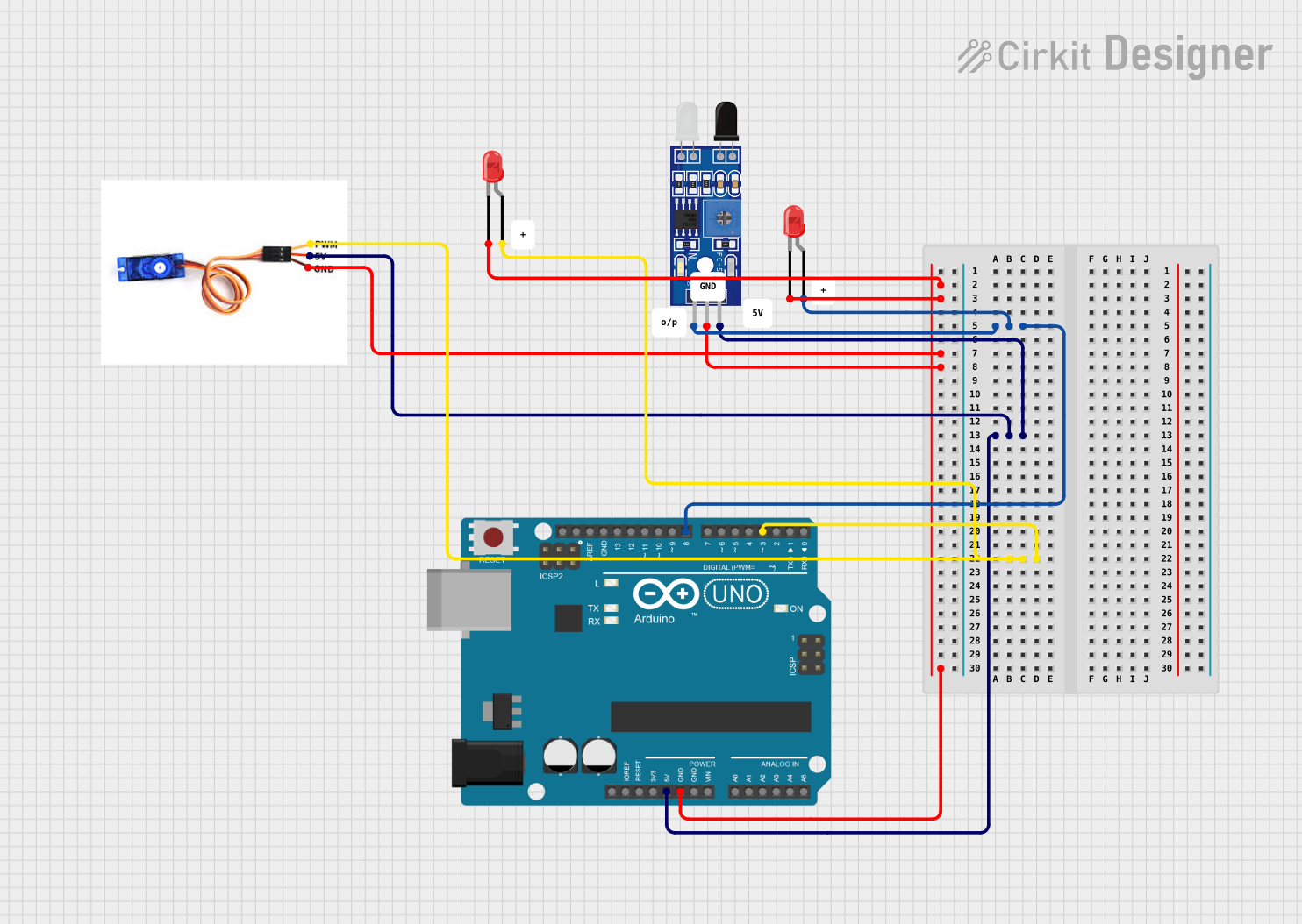
This circuit is designed to control a servo motor and two LEDs based on the input from an IR sensor. The Arduino UNO microcontroller is used to read the IR sensor output and control the servo motor and LEDs accordingly. When the IR sensor detects an obstacle, the servo motor rotates to 90 degrees for a duration of 2 seconds, and one of the LEDs lights up. The sensor is checked every 0.1 seconds for obstacle detection.
Component List
Sensor FC-51 IR
- Description: An infrared sensor used for obstacle detection.
- Pins: OUT, GND, VCC
Arduino UNO
- Description: A microcontroller board based on the ATmega328P.
- Pins: UNUSED, IOREF, Reset, 3.3V, 5V, GND, Vin, A0-A5, SCL, SDA, AREF, D0-D13
SG90 Servo Motor
- Description: A small and lightweight servo motor for precise control.
- Pins: PWM, 5V, GND
LED: Two Pin (red)
- Description: A red light-emitting diode used as an indicator.
- Pins: cathode, anode
Wiring Details
Sensor FC-51 IR
- OUT: Connected to Arduino UNO pin D8
- GND: Connected to common ground
- VCC: Connected to Arduino UNO pin 5V
Arduino UNO
- GND: Connected to common ground
- 5V: Provides power to Sensor FC-51 IR and SG90 servo motor
- D8: Receives sensor output from Sensor FC-51 IR
- D3: Controls SG90 servo motor via PWM
SG90 Servo Motor
- PWM: Controlled by Arduino UNO pin D3
- 5V: Powered by Arduino UNO pin 5V
- GND: Connected to common ground
LED: Two Pin (red)
- cathode: Connected to common ground
- anode: One LED is connected to Arduino UNO pin D8
Documented Code
/*
 * This Arduino sketch controls a servo motor and two LEDs based on input from an
 * IR sensor. When the IR sensor detects an obstacle, the servo motor rotates 90
 * degrees for 2 seconds, and the LED connected to pin D8 lights up. The sensor
 * is read every 0.1 seconds.
 */

#include <Servo.h>

// Pin definitions
const int irSensorPin = 8; // IR sensor output connected to D8
const int ledPin = 8;      // LED anode connected to D8
const int servoPin = 3;    // Servo PWM connected to D3

Servo myServo;

void setup() {
  pinMode(irSensorPin, INPUT);
  pinMode(ledPin, OUTPUT);
  myServo.attach(servoPin);
  myServo.write(0); // Initialize servo to 0 degrees
}

void loop() {
  int sensorValue = digitalRead(irSensorPin);
  if (sensorValue == HIGH) { // Obstacle detected
    digitalWrite(ledPin, HIGH); // Turn on LED
    myServo.write(90); // Rotate servo to 90 degrees
    delay(2000); // Wait for 2 seconds
    myServo.write(0); // Return servo to 0 degrees
    digitalWrite(ledPin, LOW); // Turn off LED
  }
  delay(100); // Read sensor every 0.1 seconds
}
Filename: sketch.ino
This code is written for the Arduino UNO microcontroller. It initializes the servo motor and sets up the IR sensor and LED pin modes. In the main loop, it reads the sensor value and, if an obstacle is detected, it activates the LED and moves the servo motor. After a delay, it resets the servo motor and turns off the LED before checking the sensor again.