Cirkit Designer
Your all-in-one circuit design IDE
Home /
Project Documentation
Arduino Mega 2560 and RAMPS 1.4 Based Stepper Motor Control System with Limit Switches

Circuit Documentation
Summary
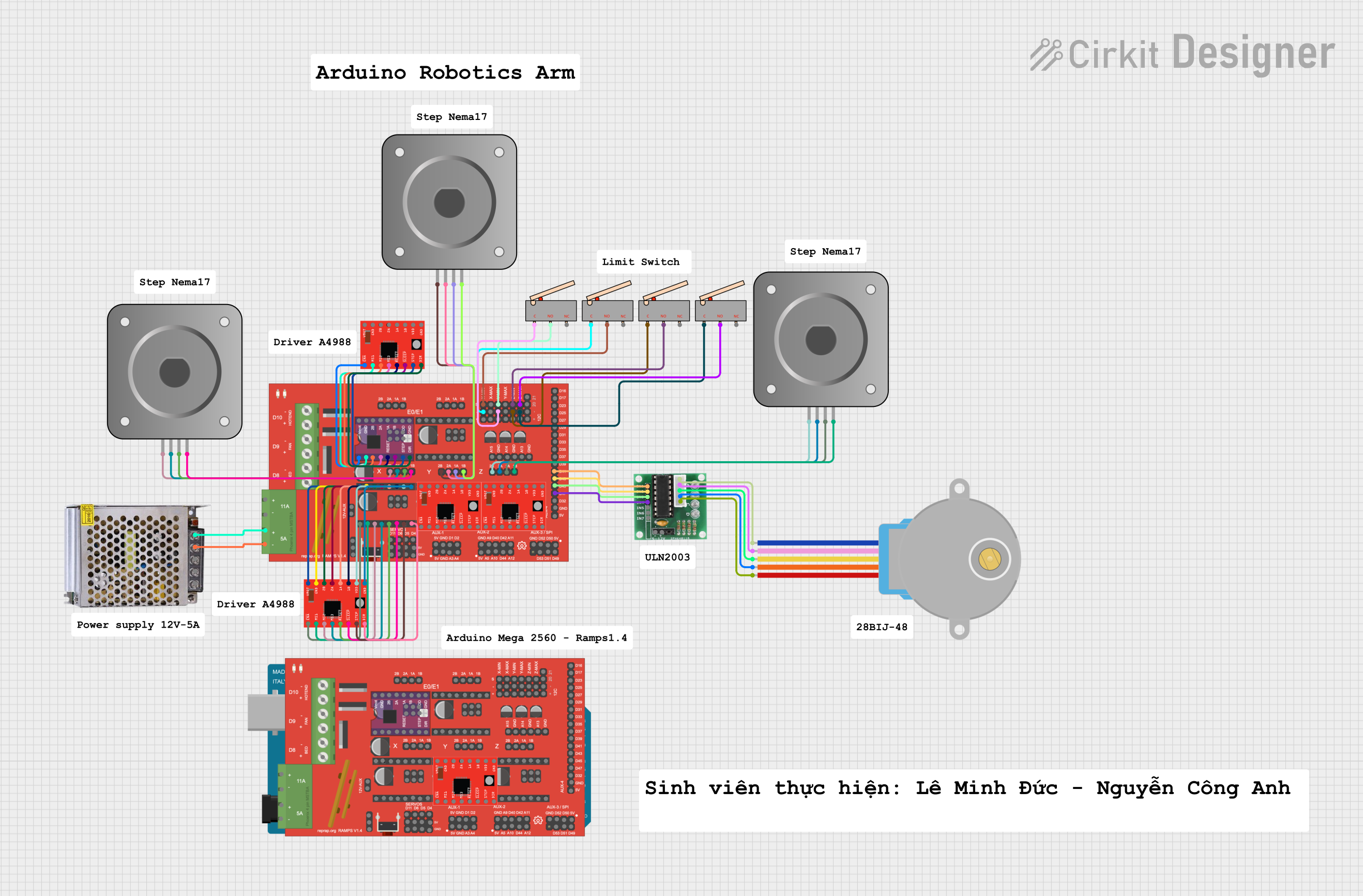
This document provides a detailed overview of a circuit designed using various components including a RAMPS 1.4 board, A4988 stepper motor drivers, bipolar stepper motors, limit switches, a ULN 2003 driver, a 28BYJ-48 stepper motor, and a 12V power supply. The circuit is controlled by an Arduino Mega 2560 microcontroller. The document includes a component list, wiring details, and the embedded code used in the microcontroller.
Component List
RAMPS 1.4
- Description: RAMPS 1.4 is a shield for the Arduino Mega, designed to control 3D printers and CNC machines.
- Pins: 2B, 2A, 1A, 1B, S, GND, VCC, SDA, SCL, 12V5A, 12V11A, THERM0, THERM1, THERM2, 5V, D11, D6, D5, D4, D1, D2, A3, A4, A9, D40, D42, A11, A5, A10, D44, A12, D52, D50, D53, D51, D49, D32, D47, D45, D43, D41, D39, D37, D35, D33, D31, D29, D27, D25, D23, D17, D16, PS-ON, MS1, MS2, MS3, Vmot, VDD, DIR, STEP, SLP, RESET, ENABLE, 12V
A4988 Stepper Motor Driver (Red)
- Description: A4988 is a microstepping driver for controlling bipolar stepper motors.
- Pins: ENABLE, MS1, MS2, MS3, RESET, SLEEP, STEP, DIR, VMOT, GND, 2B, 2A, 1A, 1B, VDD
Bipolar Stepper Motor (NEMA 17)
- Description: NEMA 17 is a standard size for stepper motors used in 3D printers and CNC machines.
- Pins: A-, A+, B+, B-
Limit Switch
- Description: A limit switch is used to detect the presence or absence of an object.
- Pins: C, NO, NC
ULN 2003
- Description: ULN 2003 is a high-voltage, high-current Darlington transistor array.
- Pins: IN1, IN2, IN3, IN4, IN5, IN6, IN7, GND, +, COIL1, COIL2, COIL3, COIL4, COIL5
28BYJ-48 Stepper Motor
- Description: 28BYJ-48 is a small stepper motor commonly used in low-power applications.
- Pins: BLUE, PINK, YELLOW, ORANGE, RED
POWER SUPPLY 12V 5AMP
- Description: A power supply unit providing 12V DC at 5A.
- Pins: 220V Positive Pole (AC), 220V Negative Pole (AC), GND, GND (DC), 12V-24V Output (DC)
Arduino Mega 2560
- Description: A microcontroller board based on the ATmega2560.
- Pins: IOREF, RESET, 3V3, 5V, GND, VIN, A0, A1, A2, A3, A4, A5, A6, A7, A8, A9, A10, A11, A12, A13, A14, A15, D21/SCL, D20/SDA, D19/RX1, D18/TX1, D17 PWM/RX2, D16 PWM/TX2, D15/RX3, D14/TX3, D0 RX0, D1 TX0, D2 PWM, D3 PWM, D4 PWM, D5 PWM, D6 PWM, D7 PWM, D8 PWM, D9 PWM, D10 PWM, D11 PWM, D12 PWM, D13 PWM, AREF, SDA, SCL, D52, D50, D48, D46, D44, D42, D40, D38, D36, D34, D32, D30, D28, D26, D24, D22, D53, D51, D49, D47, D45, D43, D41, D39, D37, D35, D33, D31, D29, D27, D25, D23
Wiring Details
RAMPS 1.4
- S connected to NO of Limit switch
- GND connected to C of Limit switch
- GND connected to GND (DC) of POWER SUPPLY 12V 5AMP
- 12V5A connected to 12V-24V Output (DC) of POWER SUPPLY 12V 5AMP
- 2B connected to A- of Bipolar Stepper Motor (NEMA 17)
- 1B connected to B- of Bipolar Stepper Motor (NEMA 17)
- 2A connected to A+ of Bipolar Stepper Motor (NEMA 17)
- 1A connected to B+ of Bipolar Stepper Motor (NEMA 17)
- D47 connected to IN4 of ULN 2003
- D45 connected to IN3 of ULN 2003
- D43 connected to IN2 of ULN 2003
- D41 connected to IN1 of ULN 2003
- Vmot connected to VMOT of A4988 Stepper Motor Driver (Red)
- GND connected to GND of A4988 Stepper Motor Driver (Red)
- 2B connected to 2B of A4988 Stepper Motor Driver (Red)
- 2A connected to 2A of A4988 Stepper Motor Driver (Red)
- 1A connected to 1A of A4988 Stepper Motor Driver (Red)
- 1B connected to 1B of A4988 Stepper Motor Driver (Red)
- VDD connected to VDD of A4988 Stepper Motor Driver (Red)
- DIR connected to DIR of A4988 Stepper Motor Driver (Red)
- STEP connected to STEP of A4988 Stepper Motor Driver (Red)
- SLP connected to SLEEP of A4988 Stepper Motor Driver (Red)
- RESET connected to RESET of A4988 Stepper Motor Driver (Red)
- MS3 connected to MS3 of A4988 Stepper Motor Driver (Red)
- MS2 connected to MS2 of A4988 Stepper Motor Driver (Red)
- MS1 connected to MS1 of A4988 Stepper Motor Driver (Red)
- ENABLE connected to ENABLE of A4988 Stepper Motor Driver (Red)
A4988 Stepper Motor Driver (Red)
- VMOT connected to Vmot of RAMPS 1.4
- GND connected to GND of RAMPS 1.4
- 2B connected to 2B of RAMPS 1.4
- 2A connected to 2A of RAMPS 1.4
- 1A connected to 1A of RAMPS 1.4
- 1B connected to 1B of RAMPS 1.4
- VDD connected to VDD of RAMPS 1.4
- DIR connected to DIR of RAMPS 1.4
- STEP connected to STEP of RAMPS 1.4
- SLEEP connected to SLP of RAMPS 1.4
- RESET connected to RESET of RAMPS 1.4
- MS3 connected to MS3 of RAMPS 1.4
- MS2 connected to MS2 of RAMPS 1.4
- MS1 connected to MS1 of RAMPS 1.4
- ENABLE connected to ENABLE of RAMPS 1.4
Bipolar Stepper Motor (NEMA 17)
- A- connected to 2B of RAMPS 1.4
- B- connected to 1B of RAMPS 1.4
- A+ connected to 2A of RAMPS 1.4
- B+ connected to 1A of RAMPS 1.4
Limit Switch
- NO connected to S of RAMPS 1.4
- C connected to