
Arduino UNO LED Control System with LCD Display and Pushbutton Interface
View and Edit Project In Cirkit Designer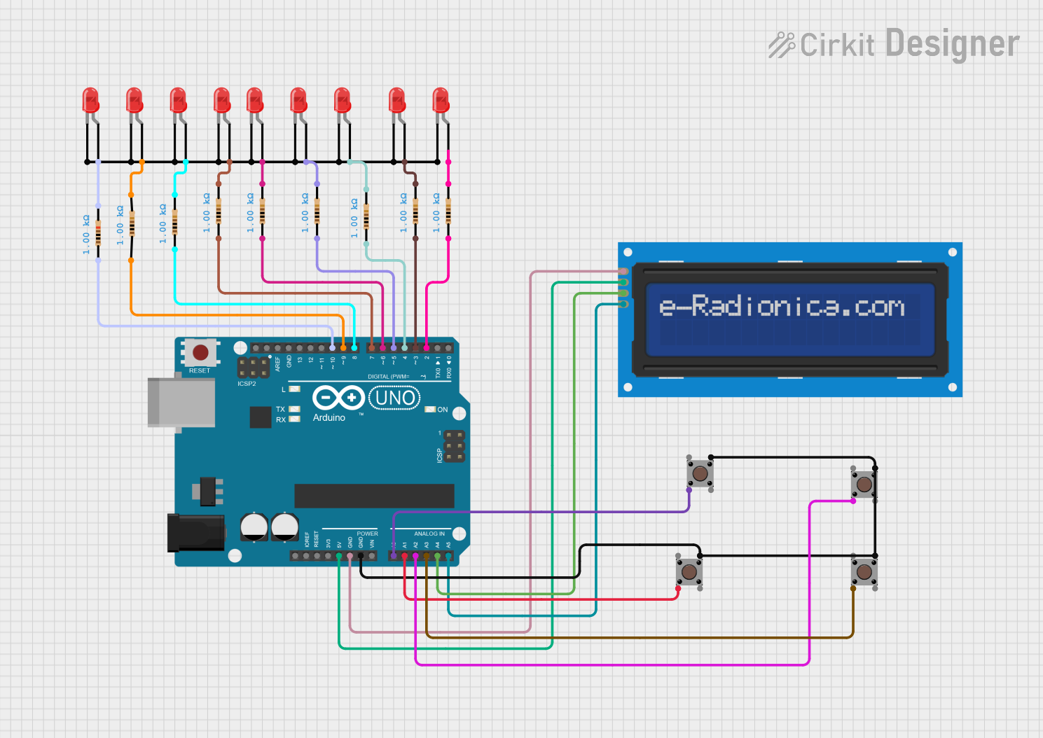
Circuit Documentation
Summary
This circuit is designed to control an array of LEDs and an LCD screen using an Arduino UNO. The user can select different modes using pushbuttons. Modes include random LED blinking at different speeds and all LEDs blinking simultaneously. The selected mode is displayed on the LCD screen.
Component List
Resistors
- Resistor (1k Ohms)
- Pins: pin1, pin2
- Description: Used to limit current to the LEDs.
LEDs
- LED: Two Pin (red)
- Pins: cathode, anode
- Description: Red LEDs used for visual indication.
Microcontrollers
Arduino UNO
- Pins: UNUSED, IOREF, Reset, 3.3V, 5V, GND, Vin, A0, A1, A2, A3, A4, A5, SCL, SDA, AREF, D13, D12, D11, D10, D9, D8, D7, D6, D5, D4, D3, D2, D1, D0
- Description: Main microcontroller used to control the LEDs and LCD screen.
LCD screen 16x2 I2C
- Pins: SCL, SDA, VCC, GND
- Description: 16x2 character LCD screen with I2C interface.
Pushbuttons
- Pushbutton
- Pins: Pin 3 (out), Pin 4 (out), Pin 1 (in), Pin 2 (in)
- Description: Used to select different modes for the LEDs.
Wiring Details
Resistors
Resistor (1k Ohms)
- pin1 connected to Arduino UNO D10
- pin2 connected to LED anode
Resistor (1k Ohms)
- pin1 connected to Arduino UNO D9
- pin2 connected to LED anode
Resistor (1k Ohms)
- pin1 connected to Arduino UNO D8
- pin2 connected to LED anode
Resistor (1k Ohms)
- pin1 connected to Arduino UNO D7
- pin2 connected to LED anode
Resistor (1k Ohms)
- pin1 connected to Arduino UNO D6
- pin2 connected to LED anode
Resistor (1k Ohms)
- pin1 connected to Arduino UNO D5
- pin2 connected to LED anode
Resistor (1k Ohms)
- pin1 connected to Arduino UNO D4
- pin2 connected to LED anode
Resistor (1k Ohms)
- pin1 connected to Arduino UNO D3
- pin2 connected to LED anode
Resistor (1k Ohms)
- pin1 connected to Arduino UNO D2
- pin2 connected to LED anode
LEDs
LED: Two Pin (red)
- anode connected to Resistor pin2
- cathode connected to common cathode net
LED: Two Pin (red)
- anode connected to Resistor pin2
- cathode connected to common cathode net
LED: Two Pin (red)
- anode connected to Resistor pin2
- cathode connected to common cathode net
LED: Two Pin (red)
- anode connected to Resistor pin2
- cathode connected to common cathode net
LED: Two Pin (red)
- anode connected to Resistor pin2
- cathode connected to common cathode net
LED: Two Pin (red)
- anode connected to Resistor pin2
- cathode connected to common cathode net
LED: Two Pin (red)
- anode connected to Resistor pin2
- cathode connected to common cathode net
LED: Two Pin (red)
- anode connected to Resistor pin2
- cathode connected to common cathode net
LED: Two Pin (red)
- anode connected to Resistor pin2
- cathode connected to common cathode net
Microcontrollers
Arduino UNO
- 5V connected to LCD screen VCC
- GND connected to LCD screen GND
- GND connected to Pushbutton Pin 3 (out)
- A0 connected to Pushbutton Pin 2 (in)
- A1 connected to Pushbutton Pin 2 (in)
- A2 connected to Pushbutton Pin 2 (in)
- A3 connected to Pushbutton Pin 2 (in)
- A4 connected to LCD screen SDA
- A5 connected to LCD screen SCL
- D10 connected to Resistor pin1
- D9 connected to Resistor pin1
- D8 connected to Resistor pin1
- D7 connected to Resistor pin1
- D6 connected to Resistor pin1
- D5 connected to Resistor pin1
- D4 connected to Resistor pin1
- D3 connected to Resistor pin1
- D2 connected to Resistor pin1
LCD screen 16x2 I2C
- VCC connected to Arduino UNO 5V
- GND connected to Arduino UNO GND
- SDA connected to Arduino UNO A4
- SCL connected to Arduino UNO A5
Pushbuttons
Pushbutton
- Pin 3 (out) connected to Arduino UNO GND
- Pin 2 (in) connected to Arduino UNO A0
Pushbutton
- Pin 3 (out) connected to Arduino UNO GND
- Pin 2 (in) connected to Arduino UNO A1
Pushbutton
- Pin 3 (out) connected to Arduino UNO GND
- Pin 2 (in) connected to Arduino UNO A2
Pushbutton
- Pin 3 (out) connected to Arduino UNO GND
- Pin 2 (in) connected to Arduino UNO A3
Code Documentation
Arduino UNO Code
// This Arduino sketch controls an array of LEDs and an LCD screen. The user can
// select different modes using pushbuttons. Modes include random LED blinking
// at different speeds and all LEDs blinking simultaneously. The selected mode
// is displayed on the LCD screen.

#include <Wire.h>
#include <LiquidCrystal_I2C.h>

// Initialize the I2C LCD (address: 0x27, columns: 16, rows: 2)
LiquidCrystal_I2C lcd(0x27, 16, 2);

// Define LED and switch pins
const int ledPins[] = {2, 3, 4, 5, 6, 7, 8, 9, 10};
const int numLeds = 9;
const int switchPins[] = {A0, A1, A2, A3};

// Variables for timing
int delayTime = 500; // Default delay for blinking
unsigned long mode4StartTime = 0;
bool mode4Active = false;

// Setup function
void setup() {
  // Initialize LCD
  lcd.init();
  lcd.backlight();

  // Set LED pins as output
  for (int i = 0; i < numLeds; i++) {
    pinMode(ledPins[i], OUTPUT);
    digitalWrite(ledPins[i], LOW);
  }

  // Set switch pins as input
  for (int i = 0; i < 4; i++) {
    pinMode(switchPins[i], INPUT_PULLUP);
  }

  // Display initial message
  lcd.setCursor(0, 0);
  lcd.print("Select a Mode");
}

// Random LED blinking function
void randomBlink(int delayTime) {
  int randomLed = random(0, numLeds);
  digitalWrite(ledPins[randomLed], HIGH);
  delay(delayTime);
  digitalWrite(ledPins[randomLed], LOW);
  delay(delayTime);
}

// All LEDs on/off function
void allLedsOnOff(int duration) {
  for (int i = 0; i < numLeds; i++) {
    digitalWrite(ledPins[i], HIGH);
  }
  delay(duration);
  for (int i = 0; i < numLeds; i++) {
    digitalWrite(ledPins[i], LOW);
  }
  delay(duration);
}

// Loop function
void loop() {
  // Check for mode switches
  if (digitalRead(switchPins[0]) == LOW) {
    // Mode 1: Random LED blink
    lcd.clear();
    lcd.setCursor(0, 0);
    lcd.print("Mode 1: Random");
    delayTime = 500; // Default speed
    mode4Active = false; // Exit mode 4
  } else if (digitalRead(switchPins[1]) == LOW) {
    // Mode 2: Slow random blink
    lcd.clear();
    lcd.setCursor(0, 0);
    lcd.print("Mode 2: Slow");
    delayTime = 100