
Circuit Documentation
Summary
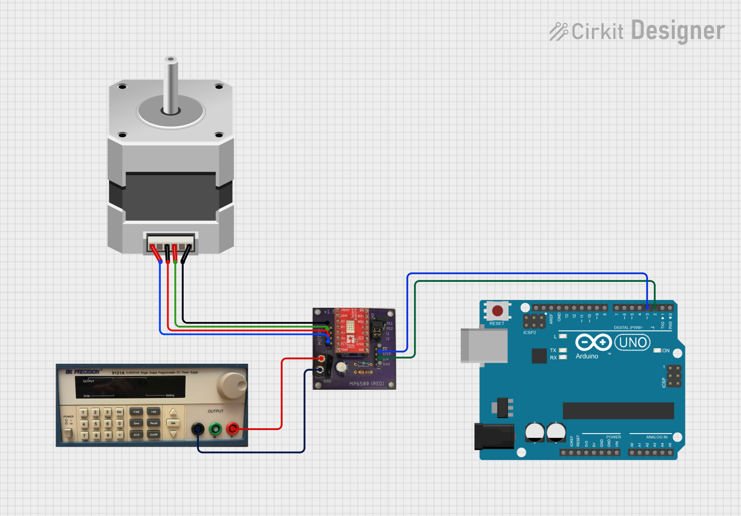
This circuit is designed to control a bipolar stepper motor using an Arduino UNO microcontroller and an MP6500 stepper motor driver. The Arduino UNO generates the step and direction signals to the driver, which in turn powers the stepper motor. A programmable DC power supply provides the necessary voltage to the motor driver.
Component List
Arduino UNO
- Description: A microcontroller board based on the ATmega328P.
- Purpose: Generates control signals for the stepper motor driver and manages the sequence of motor steps.
- Pins Used: D3, D2
Stepper Motor (Bipolar)
- Description: A bipolar stepper motor which requires a current-driven driver.
- Purpose: Executes mechanical movements as instructed by the motor driver.
- Pins Used: A, B, C, D
MP6500 (RED) Stepper Motor Driver
- Description: A stepper motor driver capable of driving a bipolar stepper motor.
- Purpose: Receives step and direction signals from the Arduino and drives the stepper motor accordingly.
- Pins Used: STEP, DIR, A1, A2, B1, B2, 12V, GND
Programmable DC Power Supply
- Description: A power supply unit that provides adjustable DC voltage.
- Purpose: Supplies power to the stepper motor driver.
- Pins Used: (Not specified in the parts list, assumed to be V+ and GND)
Wiring Details
Arduino UNO
- D3 connected to MP6500 (RED) Stepper Motor Driver's STEP pin.
- D2 connected to MP6500 (RED) Stepper Motor Driver's DIR pin.
Stepper Motor (Bipolar)
- A connected to MP6500 (RED) Stepper Motor Driver's A1 pin.
- B connected to MP6500 (RED) Stepper Motor Driver's B1 pin.
- C connected to MP6500 (RED) Stepper Motor Driver's A2 pin.
- D connected to MP6500 (RED) Stepper Motor Driver's B2 pin.
MP6500 (RED) Stepper Motor Driver
- STEP connected to Arduino UNO's D3 pin.
- DIR connected to Arduino UNO's D2 pin.
- A1 connected to Stepper Motor (Bipolar)'s A pin.
- A2 connected to Stepper Motor (Bipolar)'s C pin.
- B1 connected to Stepper Motor (Bipolar)'s B pin.
- B2 connected to Stepper Motor (Bipolar)'s D pin.
- 12V and GND connected to the Programmable DC Power Supply.
Programmable DC Power Supply
- Provides 12V and GND to the MP6500 (RED) Stepper Motor Driver.
Documented Code
// constants for the motor
const int dirPin = 2;
const int stepPin = 3;
const int STEPS_PER_REV = 200;

void setup() {
  pinMode(stepPin, OUTPUT);
  pinMode(dirPin, OUTPUT);
}

void loop() {
  digitalWrite(dirPin, HIGH);   // Motor direction clockwise

  for(int x = 0; x < STEPS_PER_REV; x++) {
    digitalWrite(stepPin, HIGH);  // Turn on the motor
    delayMicroseconds(1000);
    digitalWrite(stepPin, LOW);   // Turn off the motor
    delayMicroseconds(1000);
  }

  delay(1000);

  digitalWrite(dirPin, LOW);   // Motor direction counterclockwise

  for(int x = 0; x < STEPS_PER_REV * 2; x++) {
    digitalWrite(stepPin, HIGH);
    delayMicroseconds(1000);
    digitalWrite(stepPin, LOW);
    delayMicroseconds(1000);
  }

  delay(1000);
}
Filename: sketch.ino
Description: This Arduino sketch is designed to control a bipolar stepper motor through the MP6500 stepper motor driver. It sets the motor to rotate in one direction for one revolution, pauses, and then rotates in the opposite direction for two revolutions. The dirPin controls the direction, and the stepPin controls the stepping of the motor. The delays between steps determine the speed of the motor.