
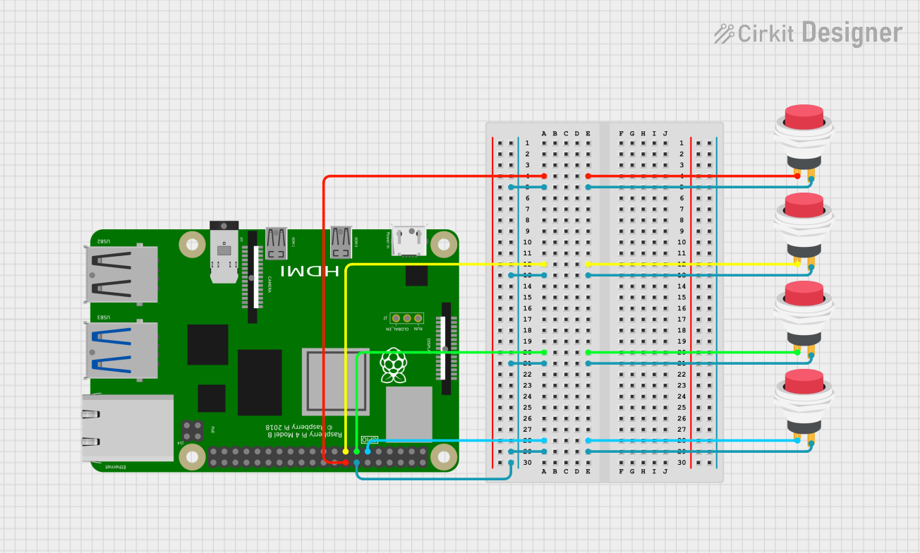
Circuit Documentation
Summary of the Circuit
This circuit is designed around the Raspberry Pi 4B, which serves as the central processing unit. The circuit includes multiple 2Pin Push Switches that are interfaced with the GPIO pins of the Raspberry Pi. These switches are used to provide input signals to the Raspberry Pi, which can be used for a variety of applications such as triggering events, starting/stopping processes, or as part of a user interface.
Component List
Raspberry Pi 4B
- Description: A powerful microcomputer with multiple GPIO pins for interfacing with various electronic components.
- Pins: 3V3, 5V, multiple GPIOs, GND, and other communication pins.
- Purpose: Acts as the main controller for the circuit, capable of processing input from switches and executing embedded code.
2Pin Push Switch
- Description: A simple push-button switch with two pins: an input and an output.
- Pins: Input +, Output +
- Purpose: Provides a user interface for sending signals to the Raspberry Pi when pressed.
Wiring Details
Raspberry Pi 4B
- GPIO23: Connected to the Input + of a 2Pin Push Switch.
- GPIO22: Connected to the Input + of a 2Pin Push Switch.
- GPIO27: Connected to the Input + of a 2Pin Push Switch.
- GPIO17: Connected to the Input + of a 2Pin Push Switch.
- GND: Common ground connected to the Output + of all 2Pin Push Switches.
2Pin Push Switches
- Switch 1:
- Input +: Connected to GPIO23 on the Raspberry Pi 4B.
- Output +: Connected to the common ground net.
- Switch 2:
- Input +: Connected to GPIO22 on the Raspberry Pi 4B.
- Output +: Connected to the common ground net.
- Switch 3:
- Input +: Connected to GPIO27 on the Raspberry Pi 4B.
- Output +: Connected to the common ground net.
- Switch 4:
- Input +: Connected to GPIO17 on the Raspberry Pi 4B.
- Output +: Connected to the common ground net.
Documented Code
Raspberry Pi 4B Embedded Code
File: sketch.ino
void setup() {
  // put your setup code here, to run once:

}

void loop() {
  // put your main code here, to run repeatedly:

}
File: documentation.txt
(No additional documentation provided for the code)
This code is a template and does not contain any functional implementation. It is expected that the user will fill in the setup() and loop() functions with the necessary initialization and main execution code to handle the input from the push switches and perform the desired actions.