
Arduino UNO-Based Smart Weighing System with Load Cell and Motor Control
View and Edit Project In Cirkit Designer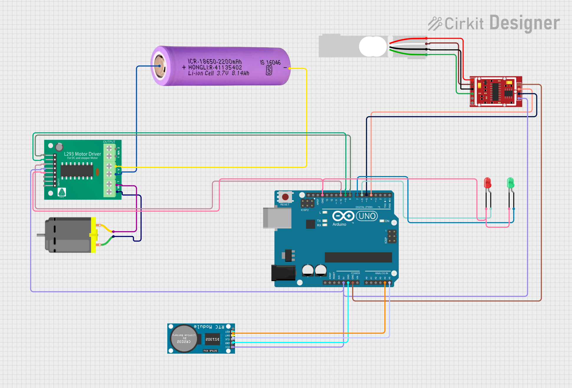
Circuit Documentation
Summary
This document provides a detailed overview of a circuit that includes various components such as a load cell, battery, LEDs, weighing sensor module, Arduino UNO, motor driver, DC motor, and an RTC module. The circuit is designed to interface these components with an Arduino UNO microcontroller, which controls the operation of the entire system. The document includes a component list, wiring details, and the embedded code used in the microcontroller.
Component List
Load Cell - Red/white/black/green
- Description: A load cell used for measuring weight.
- Pins: E+, A-, E-, A+
Battery 18650
- Description: A rechargeable lithium-ion battery.
- Pins: +, -
LED: Two Pin (red)
- Description: A red LED used for indication.
- Pins: cathode, anode
LED: Two Pin (green)
- Description: A green LED used for indication.
- Pins: cathode, anode
HX711 Weighing Sensor Module
- Description: A sensor module used to interface with the load cell.
- Pins: B-, B+, A-, A+, E-, E+, VCC, CK/TX, DO/RX, GND
Arduino UNO
- Description: A microcontroller board based on the ATmega328P.
- Pins: UNUSED, IOREF, Reset, 3.3V, 5V, GND, Vin, A0, A1, A2, A3, A4, A5, SCL, SDA, AREF, D13, D12, D11, D10, D9, D8, D7, D6, D5, D4, D3, D2, D1, D0
L293D Motor Driver
- Description: A motor driver used to control the DC motor.
- Pins: B1, B2, A1, EN_B, EN_A, A2, GND, VCC, +, -, MPIN_1, MPIN_2, MPIN_3, MPIN_4
DC Motor
- Description: A DC motor used for mechanical movement.
- Pins: pin 1, pin 2
RTC
- Description: A real-time clock module used for timekeeping.
- Pins: VCC, GND, CLK, DAT, RST
Wiring Details
Load Cell - Red/white/black/green
- E+ connected to E+ of HX711 Weighing Sensor Module
- A- connected to E- of HX711 Weighing Sensor Module
- E- connected to A+ of HX711 Weighing Sensor Module
- A+ connected to A- of HX711 Weighing Sensor Module
Battery 18650
- + connected to + of L293D Motor Driver
- - connected to - of L293D Motor Driver
LED: Two Pin (red)
- cathode connected to GND of Arduino UNO
- anode connected to D6 of Arduino UNO
LED: Two Pin (green)
- cathode connected to GND of Arduino UNO
- anode connected to D7 of Arduino UNO
HX711 Weighing Sensor Module
- VCC connected to 5V of Arduino UNO
- GND connected to GND of Arduino UNO
- CK/TX connected to D5 of Arduino UNO
- DO/RX connected to D4 of Arduino UNO
Arduino UNO
- 5V connected to VCC of HX711 Weighing Sensor Module, L293D Motor Driver, and RTC
- GND connected to GND of HX711 Weighing Sensor Module, RTC, and LEDs
- A4 connected to DAT of RTC
- A5 connected to CLK of RTC
- D10 connected to EN_A of L293D Motor Driver
- D9 connected to A2 of L293D Motor Driver
- D8 connected to A1 of L293D Motor Driver
- D7 connected to anode of green LED
- D6 connected to anode of red LED
- D5 connected to CK/TX of HX711 Weighing Sensor Module
- D4 connected to DO/RX of HX711 Weighing Sensor Module
L293D Motor Driver
- VCC connected to 5V of Arduino UNO
- GND connected to GND of Arduino UNO
- EN_A connected to D10 of Arduino UNO
- A2 connected to D9 of Arduino UNO
- A1 connected to D8 of Arduino UNO
- MPIN_1 connected to pin 1 of DC Motor
- MPIN_2 connected to pin 2 of DC Motor
- + connected to + of Battery 18650
- - connected to - of Battery 18650
DC Motor
- pin 1 connected to MPIN_1 of L293D Motor Driver
- pin 2 connected to MPIN_2 of L293D Motor Driver
RTC
- VCC connected to 5V of Arduino UNO
- GND connected to GND of Arduino UNO
- CLK connected to A5 of Arduino UNO
- DAT connected to A4 of Arduino UNO
Documented Code
Arduino UNO Code (sketch.ino)
void setup() {
  // put your setup code here, to run once:

}

void loop() {
  // put your main code here, to run repeatedly:

}
This concludes the documentation for the circuit. The wiring details and code provided should help in understanding and replicating the circuit.